
Although the built-in options often bring great enhancement to the functionality, the need for customer-specific PC elements may arise to match business unit specific applications.
An extension—in this context—is a PC element or a group of PC elements embraced from a library that can be loaded to the controller to “extend” its capabilities. If description files for Control Builder A are added, we rather speak of customer specific add-on options.
In contrast to standard options, these add-on options are usually distributed on a diskette containing:
• the option loader
• the binary image to be loaded to the controller,
• a batch file for loading the image file
• several description files for Control Builder A plus
• documentation.
The customer is able to apply the option to Advant Controller and Control Builder A himself. The loader “adds” the code to the Advant Controller’s system software during run-time.
The advantage is, that there is no need to modify the system software itself. Thereby, the only limitation for the number of add-on options is the available system FPROM memory of the processor module, respectively its RAM size.
The description files for Control Builder A are read and compiled by the Setup Add-ons Utility on the PC (for instance Advant Station 100 Series Engineering Station). An Add-on option may also be distributed together with complete PC program applications that make use of PC elements that are included in the option.
Hardware components
Basic Unit
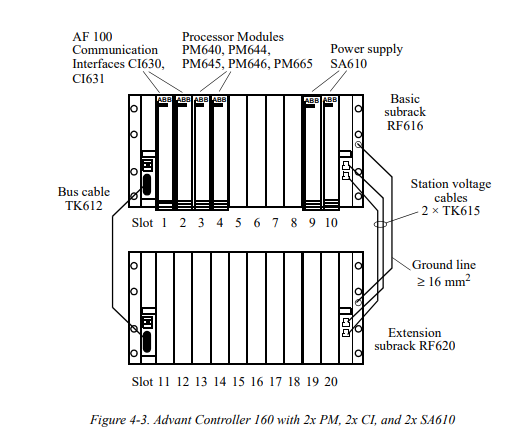
The basic subrack of the controller may consist of one or two subracks.
In accordance to the desired Advant Controller 160 functionality the Basic Unit may be equipped with a various number of the available Processor Modules and Communication Interfaces.
The following rules apply for hardware configuration of the basic station of a controller:
The two subracks must be put in the same cabinet.
The power supply terminals (USA, USB, ZD) of the two subracks must be linked. For EMI considerations, the subracks should be grounded with a 16 mm2 copper lead.
Up to six Processor Modules can be used within one Basic Unit
The Processor Modules must always be put in position 3 to 8 in the basic subrack
At least one Communication Interface module CI626, CI627, CI630, or CI631 in position 2 is required within any Advant Controller 160 configuration—even if no Advant Fieldbus 100 communication is required.
The Communication Interface module for the main Advant Fieldbus 100 must be put in position 2 (non redundant interface), or in position 1 and 2 (redundant interface) of the same subrack. Usable Communication Interfaces are CI630 or CI631 for non redundant or redundant interface, CI626 or CI627 for non redundant interface only.
The Communication Interface module for the subordinate Advant Fieldbus 100 must be put in position 9 or 10 (non redundant interface), in position 9 and 10 (redundant interface) of the same subrack. Usable Communication Interfaces are CI630 or CI631 for non redundant or redundant interface, CI626 or CI627 for non redundant interface only.
One Submodule Carrier module per controller is supported. SC610 is not supported by dual redundant Processor Modules (CPU redundancy). It requires a single Processor Module or a Processor Module of type PM645B, PM646, or PM665 within station redundancy.
If I/O stations are connected, the bus extender modules CI615 can be put in position 3…10 of the basic subrack.
Up to two optional power supply modules SA610 per subrack can be put in position 9 and 10 (basic subrack) and 19 and 20 (extension subrack).
All modules can be replaced during system operation.
For the typical Advant Controller 160 applications the following Basic Unit controller configurations are essential:
• Basic Unit with one Processor Module PM640 for non redundant processing.
Basic Unit with one Processor Module PM644 for non redundant processing with on board PROFIBUS-DP (master class 1) interface and on-board rotational speed signal input (e.g. for turbine control)
• Basic Unit with one Processor Module PM645 (type B) for dual or triple redundant processing with on-board redundancy voter and on-board rotational speed signal input (e.g. for turbine control).
– For dual redundancy an additional Processor Module PM645B within the same station or in another station is necessary
– For triple redundancy two additional Processor Modules PM645B within different stations are necessary.
Basic Unit with one Processor Module PM646 for dual or triple redundant processing with on-board redundancy voter.
– For dual redundancy an additional Processor Module PM646 within the same station or in another station is necessary.
– For triple redundancy two additional Processor Modules PM646 within different stations are necessary.
Basic Unit with one Processor Module PM665 for dual or triple redundant processing with on-board redundancy voter and on-board rotational speed signal input (e.g. for turbine control).
– For dual redundancy an additional Processor Module PM665 within the same station or in another station is necessary.
– For triple redundancy two additional Processor Modules PM665 within different stations are necessary
I/O systems
For Advant Controller 160 the S600 local I/O and the S800 distributed I/O systems are used. The maximum number of I/O signals for an Advant Controller 160 is 1,500. The actual CPU load depends on the configured cycle times for the application program.
A range of I/O modules is available, covering analog and digital signals of various types. In addition, there are modules for temperature measurement, pulse counting, position measurement and rotational speed measurement applications. The process signals are connected to the front of the I/O modules.
The controller may contain up to 75 I/O modules. All I/O modules may be exchanged during system operation. The process signals are disconnected by removing the front connector. A newly inserted module is automatically put into operation if the system identifies the module as being of the correct type and without faults. For further information about S600 I/O please refer to the S600 I/O section in the Input/Output Hardware section.
The S600 I/O Hardware Reference Guide and the S600 I/O Hardware Advant Controller 160 Reference Guide detail the various I/O modules available for Advant Controller 160.
• Unused supervised inputs
Unused supervised analog inputs of the Advant Controller 160 must be terminated with external resistors in order to avoid respective error detection and signalling by the Processor Modules.
Output set as predetermined In case of a severe controller error the outputs can be set to predetermined values. This output set as predetermined guarantees integrity of the process in case of controller failures
Output set as predetermined can be configured with use of the relay outputs of the Processor Modules which are switched over in case of a severe error. Both an open and a closed contact are provided per Processor Module. E.g. the relay outputs can be used to switch off the external voltage for digital outputs if the Processor Module which controls theses outputs fails.
S800 I/O System
A range of I/O modules is available, covering analog and digital signals of various types. The I/O system can be mounted horizontally or vertically on standard DIN-mounting rails according to DIN EN50033–35×15. The process signals are connected via module termination units, which are acting as I/O module carrier.
An I/O station may have of up to 24 I/O modules. All I/O modules may be exchanged during system operation. A newly inserted module is automatically put into operation if the system identifies the module as being of the correct type and without faults.
The general description of the I/O system is given within the Product Guide for Advant OCS with Master Software, Overview.
• Output set as predetermined In case of a severe module error, the outputs can be set to predetermined values. This output set as predetermined guarantees integrity of the process in case of failures.
Communication:For communication with other Advant Controllers, Operator Stations, and Engineering Stations, Advant Controller 160 can be connected to Advant Fieldbus 100 using the Communication Interface module CI626, CI627, CI630, or CI631. Two Communication Interfaces of type CI630 or CI631 can be used for redundancy. For communication with subordinate Advant Controllers or S800 I/O two (redundant) communication interfaces CI630 or CI631 ore via one (non redundant) communication interface CI626, CI627, CI630, or CI631 can be used.
Related product recommendations:
S-073N 3BHB009884R0021
S-097H 3BHB009885R0052
S-093H 3BHB030478R0309
S-053M 3BHB012897R0003
UFC760BE142 3BHE004573R0142
UFC718AE01 HIEE300936R0101
3BHE004573R0145 UFC760BE145
HIEE300910R0001 UFC092BE01
PPD517A3011 3BHE041576R3011
PPD517 3BHE041576R3011
3BHE040375R103E PPD115
PPD539A102 3BHE039770R0102
3BHE057901R0101 PCD235
3BHE039724R0C3D PPD513AOC-100440
PCD235C101 3BHE057901R0101
GFD563A102 3BHE046836R0102
GFD233A101 3BHE022294R0101
GFD563A101 3BHE046836R0101
GFD563A102 3BHE046836R0102
GF D563 3BHE046836R010
PPD512 A10-15000 3BHE040375R1023
More……