Description
DS200TBQCG1A – Analog IO Termination Module is available in stock which ships the same day.
DS200TBQCG1A – Analog IO Termination Module comes in UNUSED as well as REBUILT condition.
To avail our best deals for DS200TBQCG1A – Analog IO Termination Module, contact us and we will get back to you within 24 hours.
DS200TBQCG1A Other names:
Controller module DS200TBQCG1A
DS200TBQCG1A PCB module
Input/output module DS200TBQCG1A
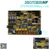
DS200TBQCG1A is an analog input terminal module developed by GE. On the R1, R2, and R3 cores, it is located at position 9. The TCQA board in each core is connected through TBQC, which also connects LVDT/R position input and 4-20 mA input. The TCQA board in the corresponding chip reads an output of 20-200 mA. By using the hardware jumper on the TBQC terminal board, the output can be set to a maximum current of 20 mA or a maximum current of 200 mA.
It has two terminal blocks, each with 83 signal wires connected. The terminal board is also equipped with 15 jumpers, three 40 pin connections, and three 34 pin connectors. The terminal can accept a total of 166 different signal line connections. TB1 and TB2 are IDs connected to the terminal block. Each terminal has a specific numerical ID.
DS200TBQCG1A connection
JBR writes the 4-20 mA input signal to the TCQA board in the corresponding core and reads the mA output signal from it.
JFR – Use LVDT/R position input signals to write relevant cores onto the TCQA board.
JBS/T – usually not used.
JFS/T – usually not used.
Testing—— Usually not used.
Hardware configuration of DS200TBQCG1A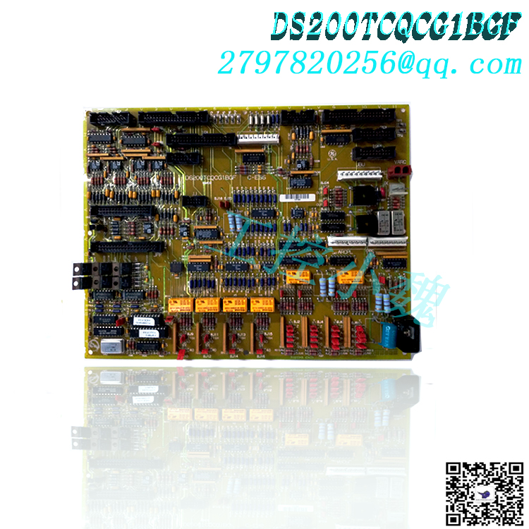
MA input signals # 1 to # 15 are connected to DCOM through BJ1 to BJ15. The BJ16 and BJ17 connectors allow you to select a maximum current output range of 20 mA or 200 mA for two mA output signals.
As mentioned above, this DS200TBQCG1A General Electric product is a printed circuit board originally produced as a member of the Mark V series. The Mark V series is a series of automatic drive components and drive component parts specifically designed for control and management systems of gas, steam, and wind turbines compatible with GE products. The Mark V turbine control system series is considered a traditional series because in the years since its initial conception, the original manufacturer ultimately discontinued the series. Although the DS200TBQCG1A printed circuit board, also known as the Mark V series PCB, is a traditional series of General Electric, it is also considered one of the final GE product lines that incorporates patented Speedtronic technology into its products. The official functional product description of this DS200TBQCG1A PCB is actually more suitable for defining it as an analog input milliampere I/O terminal module, as it appears in the original General Electric and Mark V series instruction manual materials. However, this DS200TBQCG1A module is by no means an original device in the Mark V series that has its functions; That will be the DS200TBQCG1 mother printed circuit board of the A-grade functional product revision version that lacks this DS200TBQCG1A PCB.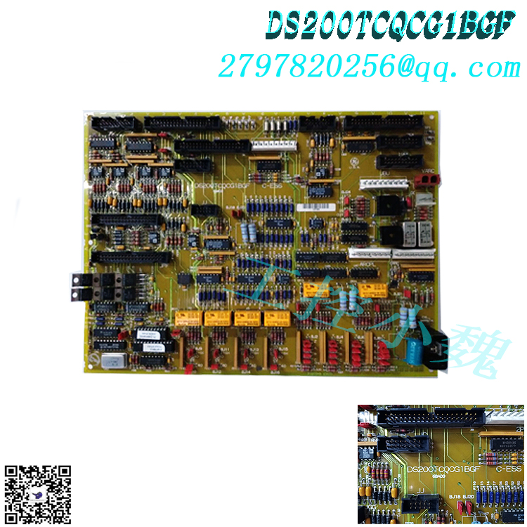
The DS200TBQCG1A module product introduces its functionality by adding a series of specific and necessary hardware options. The GE RST analog terminal board DS200TBQCG1A has 2 wiring terminals. Each terminal contains 83 signal line terminals. The GE RST analog terminal board DS200TBQCG1A also includes 15 jumpers, 3 40 pin connectors, and 3 34 pin connectors. The maximum number of signal lines you can connect to the terminal is 166. TB1 and TB2 are IDs associated with terminal blocks. In addition, each terminal is associated with a numerical ID. Therefore, to identify a specific terminal, you can use both the terminal ID and the terminal number ID. For example, TB1 83 refers to terminal 83 on terminal TB1. When you are preparing to replace the GE RST analog terminal board DS200TBQCG1A, the best practice is to prepare labels and tie them to each signal wire connected to the terminal. Write the terminal block ID and terminal digital ID on each label.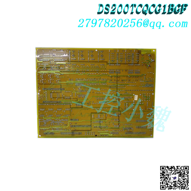
There are several important and different styles of Mark V series connectors that can be used to assemble this TBQC (abbreviated as Analog Input Milliampere I/O Terminal Module); Each connector comes with its own factory printed reference mark. These different connectors include JBR TCQA board input and output signal connectors, JFR TCQA board LVDT/R position signal connectors, JBS/T connectors, JFS/T connectors, and test connectors. You may have noticed that all of these listed connectors are named based on their compatible Mark V series interface potential, factory printed naming labels, and combinations of applications related to the DS200TBQCG1A board itself and the larger Mark V turbine control system series. The JBS/T, JFS/T, and TEST connectors included in this DS200TBQCG1A analog input milliampere I/O terminal module component are not named as such because they are not typically used in the regular functionality of this DS200TBQCG1A analog input milliampere I/O terminal module and should be considered as residual structures and ignored. The connector is not the only relevant hardware component detailed in the DS200TBQCG1A module instruction manual material, as hardware selection is achieved through a total of 15 jumpers included in this DS200TBQCG1A PCB, which have factory printed naming labels ranging from BJ1 to BJ17. These jumpers and any other hardware components on the basic circuit board of this DS200TBQCG1A product should receive some form of protection from the normal type of PCB protective coating on this DS200TBQCG1A PCB, which wraps and protects various hardware components on the DS200TBQCG1A module basic circuit board according to functional priority.
Frequently Asked Questions
What is DS200TBQCG1A?
DS200TBQCG1A is an analog input terminal module developed by GE. DS200TBQCG1A
What is the function of?
It connects the 4-20 mA input and LVDT-R position input to the TCQA board.
What is the number of terminal signals?
There are three types of terminal signals. The input and output signals are measured in milliamps, as well as the LVDT input signal.
Which of the DS200TBQCG1A connectors are rarely used?
JBS/T, JFS/T, and Test are not commonly used connections.
What is the function of DS200TBQCG1A?
DS200TBQCG1A writes 4-20 mA input and LVDT/R position input into the TCQA board in their respective cores.
Which connections on DS200TBQCG1A are usually not used?
Connecting JBS/T, JFS/T, and Test is a connection that is not typically used on DS200TBQCG1A.
All products on this website are special products, and market prices have been fluctuating,
Please refer to the customer service quotation for details, as the product is new and the price is not genuine,
Please confirm the model, product, price, and other detailed information with customer service before placing an order. The website has been used,
The new one is for sale, please contact customer service for further communication.
Model recommendation:
DS200TCQCG1BBA
DS200TCQBG1B
DS200TBQCG1AAA
DS200TCQBG1BCA
DS200TCCBG3BED
DS200TCQAG1BHF-W01
DS200TCQAG1BHF-W01
DS200TCDAH1BHE
DS200TCQBG1BCB
DS200TCPSG1AEE
DS200FSAAG1ABA
DS200SHVMG1AFE
DS200LDCCH1AKA
DS200SI0CG1A6A
DS200SHVMG1AGE
DS200SI0CG1AEA
DS200PCCAG1ACB
DS200UCPBG6AFB
DS200TCQCG1BJF
DS200DCFBG1BLC
more……


-300x300.jpg)
admin –
DS200TBQCG1A is an analog input terminal module developed by GE. On the R1, R2, and R3 cores, it is located at position 9. The TCQA board in each core is connected through TBQC, which also connects LVDT/R position input and 4-20 mA input. The TCQA board in the corresponding chip reads an output of 20-200 mA. By using the hardware jumper on the TBQC terminal board, the output can be set to a maximum current of 20 mA or a maximum current of 200 mA.
It has two terminal blocks, each with 83 signal wires connected. The terminal board is also equipped with 15 jumpers, three 40 pin connections, and three 34 pin connectors. The terminal can accept a total of 166 different signal line connections. TB1 and TB2 are IDs connected to the terminal block. Each terminal has a specific numerical ID.