
Description
Install the First Chassis and Its Components When you install an enhanced redundancy system, install one chassis, and its necessary components, at a time. Module Placement and Partnering Each pair of controllers and communication modules must be comprised of compatible partner modules. Two modules in the same slot are considered as compatible partners only if they contain compatible hardware and firmware and other rules that can be enforced by the module itself. The compatibility status (Compatible or Incompatible) is determined by either the module in the primary chassis or its partner in the secondary chassis. The redundancy module pair must occupy the same slots in their respective chassis. The redundancy module pair does not consider the chassis pair to be partnered if the redundancy modules are placed in different slots, even if the partners of other modules are present in the same slot. The redundancy module prevents certain redundancy operations, such as Qualification, if incompatible modules reside in the redundant-control chassis pair
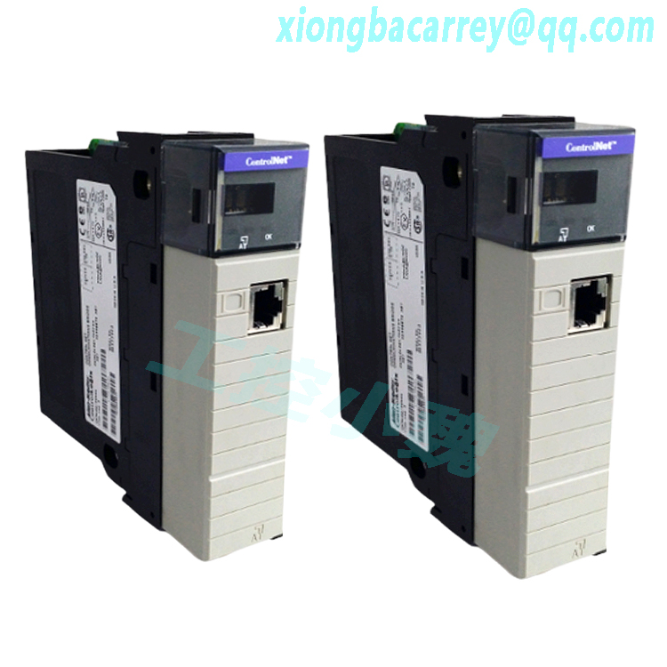
Do not apply power to the system until both chassis and their components are installed.1. Install the chassis and power supply. 2. Install the communication modules. 3. Install a controller. 4. Install the redundancy module. a. Align the circuit board with top and bottom guides in the chassis. b. Slide the module into the chassis and make sure that the module backplane connector properly connects to the chassis backplane. The module is properly installed when it is flush with other installed modules.
.jpg)
Connect the Fiber-optic Communication Cable to the Redundancy Modules Follow this procedure to install the fiber-optic communication cable to the channels of the redundancy module. 1. Remove the black protective channel cover on the first redundancy module in the redundant chassis pair. 2. Remove the protective caps from the cable ends. 3. Plug the cable connector into the CH1 or CH2 port on the first redundancy module.
.jpg)
4. Plug the other end of the cable into a channel on the secondary module. IMPORTANT The redundancy module communication cable contains optical fibers. Avoid making sharp bends in the cable. Install the cable in a location where it cannot be cut, run over, abraded, or otherwise damaged. If redundant channels between the redundancy modules are required, repeat the installation process for the unused port (CH1 or CH2) with a different fiber cable. We recommend that you match channel to channel, CH1 to CH1 and CH2 to CH2, for troubleshooting simplicity, but this match is not required.
.jpg)
Model recommendation:

Reviews
There are no reviews yet.