Description
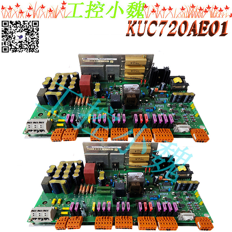
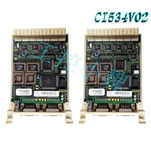
Detailed information for: 3BHB005922R0001This page contains technical data sheet, documents library and links to offering related to this product. If you require any other information, please contact us using form located at the bottom of the page.Print… Print to Pdf… Data Sheet Downloads3BHB005922R0001 General Information Product ID:3BHB005922R0001 ABB Type Designation:- Catalog Description:UNS 0880a-P,V1:CIN PCB completed Long Description:UNS 0880a-P,V1:CIN PCB completed Additional Information ABB Type Designation:- Country of Origin:Switzerland (CH Customs Tariff Number:8537109 Frame Size:Undefined Gross Weight:0 kg Invoice Description:UNS0880a-P,V1:CIN PCB completed Made To Order:No Minimum Order Quantity:1 piece Order Multiple:1 piece Package Level 1 Gross Weight:0 kg Package Level 1 Units:1 piece Part Type:New Product Name:- Product Net Depth / Length:445 mm Product Net Height:45 mm Product Net Weight:0.62 kg Product Net Width:230 mm Product Type:Undefined Quote Only:No Selling Unit of Measure:piece Stocked At (Warehouses):Baden, Switzerland
.jpg)
WEEE Category:Product Not in WEEE Scope
This document provides a detailed description of the ABB KUC711AE101 product. ABB KUC711AE101 is a high quality electrical component designed for various applications. It is a control unit that integrates a programmable logic controller and a human-machine interface. Some key features of the ABB KUC711AE101 include:
-Compact design -High processing power -Extensive communication options -Integrated web server -Fast Ethernet port -Multiple programming languages -Real time clock -High resolution display need. It is a reliable and robust control unit that can be customized to meet specific requirements. With its user-friendly interface, high processing power and advanced features, the ABB KUC711AE101 is an excellent choice for anyone looking for a high-quality control unit.
.jpg)
The ABB KUC711AE101 is designed to operate in harsh environments and is suitable for a variety of industries including manufacturing, oil and gas, and transportation. It is a reliable and robust product that can withstand extreme temperatures, vibration and shock.
The control unit is easy to use and equipped with a user-friendly interface. It has been designed to be intuitive and can be used by both experienced and inexperienced operators. ABB KUC711AE101 can be customized to meet specific requirements and programmed to perform various tasks.
This document provides a detailed description of the ABB KUC711AE101. ABB KUC711AE101 is a high-performance programmable logic controller (PLC) designed to provide reliable and efficient automation solutions for industrial applications.
ABB KUC711AE101 is equipped with a powerful processor and a series of communication interfaces, which is very suitable for use in complex industrial environments. It has a large storage capacity and can store complex programs and data.
PLCs also feature a high level of security, with advanced encryption and authentication mechanisms to prevent unauthorized access. It is designed to be extremely durable and able to withstand harsh industrial environments.
With its user-friendly interface and intuitive programming software, ABB KUC711AE101 is easy to use and program, making it an ideal solution for both experienced and novice users.
ABB KUC711AE101 is a reliable and efficient PLC designed to meet the demands of modern industrial automation applications.
AC drives are used to control the speed and torque of standard induction motors, which are staples in industry. ABB is the market leader in the field of variable frequency controllers and electric motors worldwide.
The AC frequency conversion technology extends the speed range of the motor—from zero to much higher than the rated speed—so that the production efficiency of the driven process is significantly improved. In cases where only a lower capacity is required, the frequency converter saves energy by reducing the speed of the motor.
ABB standard drives are easy to purchase, install, set up and use, saving a lot of time. They are widely available at various ABB distributors and are therefore called standard drives. These frequency converters have common customer and process interfaces with the fieldbus, common software tools for dimensioning, commissioning and maintenance, and common spare parts.
Inverter is a high-precision, high-tech electronic component. We should also analyze and repair its faults from the simple to the complex. For our general on-site maintenance personnel, it is not necessary to have a deep understanding of its faults. The internal structure, but the law of its general failure should be grasped for analysis and treatment.
When the frequency converter fails, we should first read the fault code from the display panel of the frequency converter. The code information of each type of frequency converter of this type of code will not be consistent, but there will basically be overcurrent, overvoltage, overload and loss of voltage. , over temperature, analog loss, communication loss and other fault records. In the ABB-ACS550 inverter, the historical fault records can be checked through the parameters of group 04. At the same time, when there is a general failure, we can judge from the indicator light on the panel turning red.
When analyzing the fault, we can also check the actual switch signal, analog signal and actual inverter operation data from the actual detection data of the inverter to judge whether it is normal. The inspection of such signal values of the ABB-ACS550 inverter can be done in Parameter group No. 01 is found.
In addition, we should pay attention to whether the characteristic parameters of frequency conversion are set reasonably, especially the settings of U/F curve, acceleration and deceleration time, current limit, and various protection parameters need to be checked and analyzed.
One inverter controlled by DCS, after the operator set the operating frequency to 30Hz and turned it on, he found that the actual speed of the motor was very slow, and even tripped to a stop.
Analysis and treatment: Since the original control is normal, it means that the original external wiring and control method should be fine. Check the fault code of the inverter for overcurrent and overload. The possible reason is that the load is too large. According to the feedback obtained on site, there is no problem with the motor. Due to the change of the process, the load of the inverter is increased. Check the current limit of the inverter and it is normal. Check the operating parameters in the trial operation and find that the input switch and analog data are normal, but when the input analog is about 30Hz, the output frequency is higher. If not, it is obvious that the starting belt load capacity of the inverter is poor, adjust the U/F curve to increase the voltage at low frequency when starting, and the fault is eliminated.
One inverter often tripped and stopped during operation, reporting an over-temperature alarm.
Analysis and treatment: Since the inverter was running normally in the early stage, the over-temperature alarm trip is generally only caused by the inverter running at full load for a long time and cannot fully dissipate heat. Check the motor load is normal, but when the inverter is removed for inspection, it is found that the heat sink on the inverter The dust is very thick, which seriously hinders the heat dissipation performance of the inverter. After the dust is fully washed, the inverter will work normally.
It can be seen from the example that our maintenance of the inverter is not complicated. Some routine small problems are not the inverter itself, but we do not pay attention to its operating environment. The real burnout of the inverter is also under the premise that these environments are not guaranteed , caused by accelerated aging of its internal components. Therefore, we should especially check the working condition of the frequency converter during normal maintenance, and keep the surrounding environment dust-free, water-free, corrosion-free and constant temperature.
Generally, we call the process of forming the rotating magnetic field of the primary rotor of the generator according to the principle of electromagnetic induction as excitation. In addition, providing a working field for generators and other “electrical equipment that works on the principle of electric shock” is also called excitation. Sometimes, the device that provides rotor power to the generator rotor is also called excitation.
With the development of power construction, China’s power system industry has entered the stage of large network, high voltage, and large units. The stability of large-capacity generating units during operation is crucial to the stability and security of the overall power grid. However, it is the motor excitation system that greatly affects the stability of the generator. The excitation system plays a very important role in the safety of the power grid. It is not only a guarantee for the stable operation of the unit, but also a lever for reactive power and voltage regulation in the entire power grid.
Model recommendation:


-300x300.jpg)
Reviews
There are no reviews yet.