Description
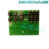
DS200SHVMG1AFE – Power Connect Card is available in stock which ships the same day.
DS200SHVMG1AFE – Power Connect Card comes in UNUSED as well as REBUILT condition.
To avail our best deals for DS200SHVMG1AFE – Power Connect Card, contact us and we will get back to you within 24 hours.
DS200SHVMG1AFE Other names:
Input/output module DS200SHVMG1AFE
DS200SHVMG1AFE Controller Module
Analog module DS200SHVMG1AFE
Function Description
DS200SHVMG1AFE is a power connection card developed by GE. It is part of the EX2000 system. This card is a key component in the complex design of the drive system, serving as an intermediary between the driver control circuit and the SCR power bridge. This interface is crucial for seamless integration and efficient operation of the drive, ensuring controlled and optimized power flow.
Features
A significant feature of this board is the use of pulse transformers to provide necessary gate drive for the SCR power bridge. This gate drive helps regulate the triggering sequence and control of SCR, thereby managing the power flow in the system. The pulse transformer is a key link in this process, which helps to achieve precise and controllable communication between the control circuit and the power bridge.
For low to medium power controllers, the board goes further by adding buffer circuits. These circuits play a crucial role in managing and controlling voltage spikes at various critical points within the system. Specifically, they solve the spike problem on AC lines, DC buses, and gate drivers. By directly integrating these buffer circuits into PCCA, the system gains enhanced protection and stability, especially in managing low to medium power levels.
However, for controllers with higher power, the design may vary. In this case, some or all of the buffer circuits will be omitted. On the contrary, these circuits will be placed elsewhere in a broader system architecture. This strategic decision is made to optimize the overall design, efficiency, and performance of higher power controllers, allowing for the adoption of more decentralized and specialized buffer circuit methods.
Hardware configuration
Configurable jumpers: This board is equipped with configurable jumpers, allowing users to customize specific settings and connections according to the requirements of the drive system. Jumper is a small connector that can be installed on designated pins on a board to establish or interrupt electrical pathways. This kind of configurability is very advantageous because it can adapt to different system configurations and operational requirements..jpg)
Wiring plug connector: Wiring plug connector is another component of hardware. These connectors help establish safe and reliable electrical connections between the circuit board and other components within the drive system. By using these connectors, the installation and maintenance process is simplified, allowing for efficient assembly and disassembly when needed. The use of plug connectors can enhance the modularity of the system, simplify initial settings and future modifications.
No LEDs, fuses, test points, or switches: Unlike some other electronic boards, PCCA intentionally omits certain components such as LEDs, fuses, test points, and switches. LEDs are usually indicator lights, fuses are used to prevent overcurrent, test points are used for diagnosis, and switches are used to control specific functions. The absence of these components on the PCCA board indicates that it relies on the configurability of jumpers and the simplicity of plug connectors to achieve customization and connection purposes.
Configurable jumper cables
JP1 and JP2 jumpers: These two jumpers JP1 and JP2 are crucial components that need to be connected to appropriate insertion terminals P3 to P10. The specific connection depends on factors such as the card group number and system voltage. Proper configuration of JP1 and JP2 is crucial for establishing the correct electrical pathway and ensuring compatibility with the unique specifications of the power system. These jumpers essentially act as switches, guiding the flow of current based on determined parameters.
WP3 and WP4 jumpers: WP3 and WP4 have different purposes, connecting P2A to P2B and P1A to P1B respectively. These jumpers play a crucial role in the selection process, determining whether the PCCA buffer capacitor is connected to the same point on the power bridge as a voltage feedback channel. This configuration is crucial for effectively managing and controlling voltage spikes. In this case, jumpers provide a method of customizing buffer capacitor connections based on specific requirements of the power system, thereby enhancing the overall stability and performance of the system.
Hardware tips and specifications
The GE DC power connection board DS200SHVMG1AFE is used as the interface between the driver and the SCR power bridge. Before replacing the DS200SHVMG1AFE board, in order to fully utilize the GE DC board, please check the diagnostic information provided on the drive to verify if there are any defects or if repairs are needed. The first diagnostic indication of a malfunction in the Mark V series driver involving this PCB may be a trip condition on the driver. For example, if the drive overheats, the motor will shut down and a message will be displayed indicating the problem. If this situation occurs, corrective measures include checking the ventilation of the drive and the temperature of the surrounding equipment. Another fault indication is the LED indicator light on the control panel attached to this device. If the LED indicator light is on, it indicates a fault condition has occurred. Drive diagnostics (also available through the control panel) provide information on various aspects of drive operation. Diagnosis is a read-only file that can help you identify any issues..jpg)
The DS200SHVMG1AFE does not come with fuses, indicator lights, test points, or switches, so the opportunity to troubleshoot the circuit board is limited. However, the circuit board does contain four jumpers that can be used to configure the behavior of the circuit board in the driver. By using these labeled jumpers, you can configure the operations related to capacitors, power bridges, and voltage feedback channels. The last highlighted hardware element used in the assembly of this DS200SHVMG1AFE power connection card component must be considered as its specific armature electrical compression and discharge. This DS200SHVMG1AFE PCB has armature voltage scaling ranging from 240 to 630 volts regenerative voltage, as revealed in the first group of Mark V series products included in this product. All of the above hardware elements and specifications should receive at least some form of basic daily wear and tear protection to prevent the standard common PCB protective coating used during the assembly of the DS200SHVMG1AFE power connection card component.
Frequently Asked Questions
What is the DS200SHVMG1AFE interface used for?
DS200SHVMG1AFE is the interface between the driver control circuit and the SCR power bridge.
What is the armature voltage on DS200SHVMG1AFE ?
The DS200SHVMG1AFE has an armature voltage of 240-630 volts and is regenerative.
What types of fuses are available for DS200SHVMG1AFE ?
DS200SHVMG1AFE is equipped with a circuit fuse. The G1, G2, G7, and G8 PCCA board groups, including the DS200SHVMG1AFE , have line fuses, while G5, G6, G9, and G10 have pin fuses.
Which manual is helpful for DS200SHVMG1AFE ?
The useful manual for using DS200SHVMG1AFE is the GEI-100161- GE Industrial Control System PCCA Power Connection Card Manual. This manual is specifically designed for DS200SHVMG1AFE . Although it does not cover all procedures related to the installation, operation, and maintenance of DS200SHVMG1AFE , it provides good general information about DS200SHVMG1AFE . This manual has a detailed functional description, which describes the application data of DS200SHVMG1AFE , and introduces the renewal/warranty replacement information of DS200SHVMG1AFE for DS200SHVMG1AFE .
What is DS200SHVMG1AFE ?
It is a Power Connect Card developed by GE under the EX2000 series.
What are the designated jumpers on the PCCA board?
This board has four wire jumpers designated as JP1, JP2, WP3, and WP4.
What is the function of JP1 and JP2 jumper wires?
The JP1 and JP2 jumpers play a crucial role in selecting system voltage and determining specific electrical connections. The correct configuration is crucial for aligning with the card group number and system voltage.
How can JP1 and JP2 jumpers help with system customization?
By connecting JP1 and JP2 to appropriate insertion terminals P3 to P10, these jumpers allow users to customize electrical pathways based on card group numbers and system voltage, ensuring compatibility with specific power system requirements.
What is the purpose of WP3 and WP4 jumpers on PCCA?
The WP3 and WP4 jumpers are crucial for determining the connection of buffer capacitors. They help to select whether the buffer capacitor is connected to the same power bridge point as the voltage feedback channel.
All products on this website are special products, and market prices have been fluctuating,
Please refer to the customer service quotation for details, as the product is new and the price is not genuine,
Please confirm the model, product, price, and other detailed information with customer service before placing an order. The website has been used,
The new one is for sale, please contact customer service for further communication.
Related product recommendations:
DS200UCPBG6AFB
DS200TCQCG1BJF
DS200DCFBG1BLC
DS200DCFBG2BNC
DS200DCFBG1BNC
DS200DCFBG2BNC
DS200FECBG1A
DS200DDTBG1A
DS200DDTBG1
DS200SHCAG1B
IS200WEORG1A
IS200ESELH1A
IS200AEPGG1AAA
IS200TSVCH2AED
IS200EPMCH1
IS200JPDGH1A
IS200ECTBG1ADE
IS200WETAH1AGC
IS200EXHSG3REC
IS200JPDSG1A
more……


-100x100.jpg)
-100x100.jpg)
-300x300.jpg)

-300x300.jpg)

Reviews
There are no reviews yet.