Description
IS200VCRCH1B IS200VCRCH1BBC – Analog Input Terminal Board is available in stock which ships the same day.
IS200VCRCH1B IS200VCRCH1BBC – Analog Input Terminal Board comes in UNUSED as well as REBUILT condition.
To avail our best deals for IS200VCRCH1B IS200VCRCH1BBC – Analog Input Terminal Board, contact us and we will get back to you within 24 hours.
Product Description
IS200VCRCH1B IS200VCRCH1BBC is a GE Mark VI board component. MKVI is part of the Speedtronic series of gas and steam turbine management systems, which have been developed and improved by General Electric since the release of Mark I in the 1960s. MKVI is the fifth management system in the Speedtronic series, with triple redundant control for all protection parameters and critical controls, as well as advanced control mechanisms for protecting and monitoring turbine systems.https://www.weikunfadacai1.com/
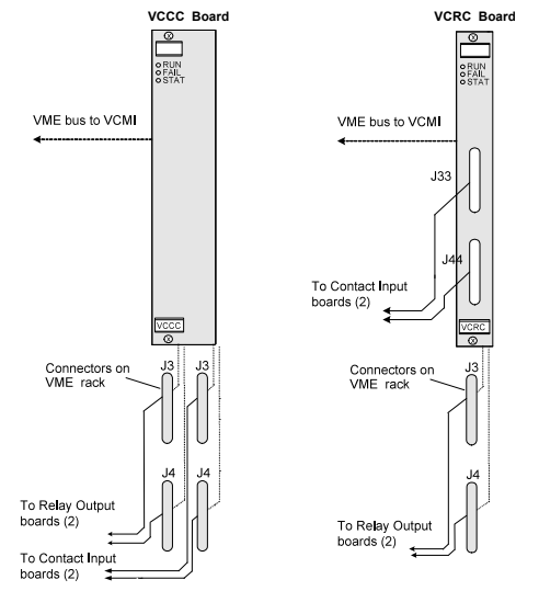
IS200VCRCH1B IS200VCRCH1BBC is used as a discrete input/output board. This is a single slot board that has the same functions as a VCCC board, but does not include sub boards, thus occupying less rack space. However, since the relay output of the board uses the J3/J4 ports on the VME rack, the cables must be placed on the front panel. If you do not want this situation to occur, please use a VCCC board instead of a VCRC PCB.
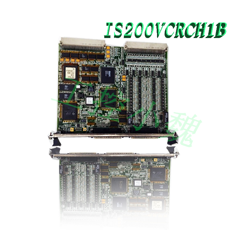
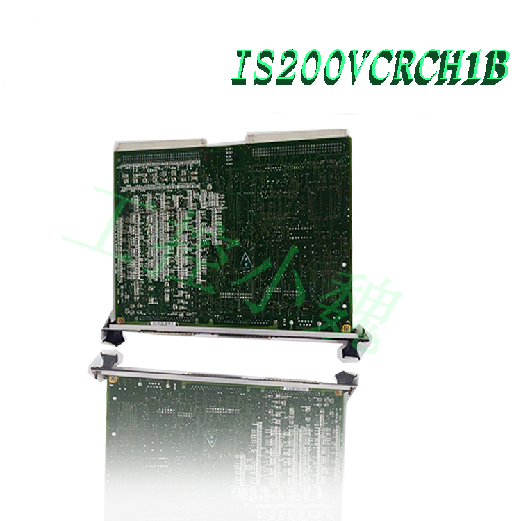
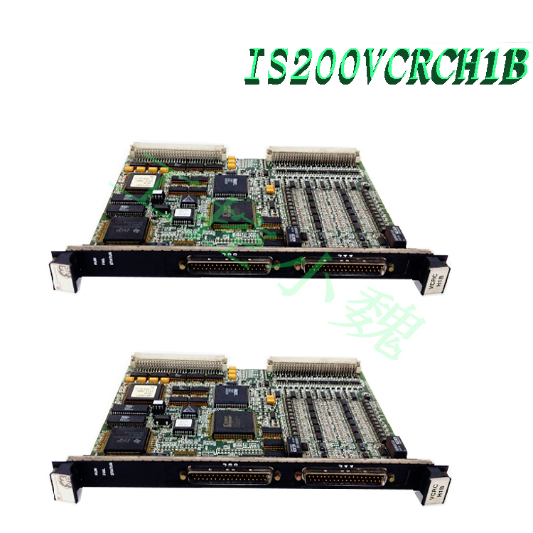
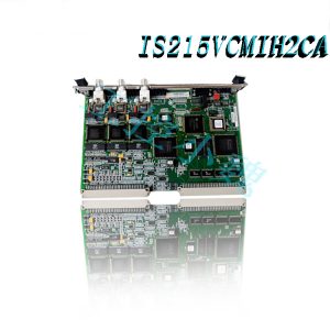
The surface of IS200VCRCH1B is equipped with two backplane connectors. There are multiple conductive connectors (P4 to P6) on the surface of the board. The board also includes resistors, diodes, capacitors, and TP test points. This board has over thirty transistors and two power supplies. The integrated circuits located on the surface of the board include FPGA and various SRAM and RAM chips. For more information about IS200VCRCH1B, please refer to the data sheet, manual, or Mark VI control system guide.
IS200VCRCH1B is a contact input/relay output board manufactured by General Electric and is part of the Mark VI series used in gas turbine control systems. The contact input/relay output board accepts 48 discrete inputs and manages 24 relay outputs from a total of four terminal boards through its accompanying sub boards. The dual width VCCC module is installed in the VME I/O rack. Two sets of J3/J4 connections are provided in this rack for connecting to TBCI and TRLY terminal boards. VCRC is a narrower board that can be used instead of VCCC.
Contact input
The contact input terminal board (TBCI) is used for the first 24 dry contact inputs; Input 25-48 requires a second terminal block. The contacts provide DC power. The terminal board is connected to the VME rack equipped with a VCCC processor board through a cable with a molded plug. For monitoring inputs of key turbine variables, high-speed scanning and recording can be performed at 1 millisecond per second. The Event Sequence (SOE) recorder can report contact tremors and pulse widths as low as 6 ms, as well as all contact opening and closing with a time resolution of 1 ms.
Relay output
TRLYH1B stores 12 plug-in magnetic relays. Jumpers can be used to set the first six relay circuits to drive external solenoid or dry C-type contact outputs. For on-site solenoid valve power supply, standard 125 V DC or 115 V AC power supply and optional 24 V DC power supply can be provided, with separate jumper optional fuses and onboard suppression. The following five relays (7-11) have independent C-type contacts that are not energized. Output 12 uses isolated C-type contacts for special applications such as ignition transformers.
VCRC Options
The VCRC board has the same functionality as the VCCC board, but since no sub board is required, only one VME slot is required. The contact inputs of the TBCI board are received by two front panel connections J33 and J44. Similar to VCCC, the relay output on TRLY is connected to the J3 and J4 ports on the VME rack. If not required, VCCC can be used instead of the cable layout on the front panel.
Installation of IS200VCRCH1B board
Turn off the processor rack for VME I/O.
To secure the edge connector, slide in the VCCC board and manually push in the top and bottom control levers.
Tighten the self tapping screws at the top and bottom of the front panel.
Open the VME rack and view the front panel diagnostic indicators.
Operation of IS200VCRCH1B board
The input voltage in VCCC is sampled at the frame rate used to control the function after passing through the optical isolator, and reported as SOE at 1 ms. The signal is transmitted to VCMI through the VME backplane. Next, the controller receives them from VCMI. The processing process of contact input is shown in the following figure. The dry contact input is powered by a floating 125 V DC (100-145 V DC) power supply.
Filter each input control surge and reduce high-frequency noise near the signal outlet. A 4 ms filter is used to filter out noise and contact bounce. When using 125 V DC excitation, the AC voltage suppression (50/60 Hz) is 60 V RMS.
For TMR applications, plugs JR1, JS1, and JT1 provide contact input voltage for the three VME board racks R, S, and T. Once three VCCCs analyze the signal, the VCMI board of each controller rack will vote on the results. The relay control signal and monitoring feedback voltage are transmitted between VCCC and TRLY through cables.
The relay board is equipped with relay drivers, fuses, and jumpers. TRLY, DRLY, and SRLY are just a few different types of relay boards that can be driven. The fault safety function on the relay output allows the input to vote to power off the corresponding relay when the cable is unplugged. If communication with the connected VME board is lost, the relay will also be powered off.
Frequently asked questions
Why do turbines require monitoring and speed control?
Atomic power plants generate heat through nuclear fusion, and water is heated to generate steam to power turbines. To maintain frequency F, it is necessary to maintain a constant speed of 1500 RPM. Family settings are affected by frequency changes.
What is the function of a printed circuit board PCB?
Printed Circuit Board (PCB) is a device that uses conductive paths, tracks, or signal wires etched from copper sheets laminated onto non-conductive substrates to mechanically support and electrically connect electronic components.
What is the analog output module in PLC?
PLC output module. PLC analog outputs are widely used in industrial applications for operating actuators, valves, and motors, using typical analog output ranges such as 5 V, 10 V, 0 V to 5 V, 0 V to 10 V, 4 to 20 mA, or 0 to 20 mA.
Where can I buy printed circuit boards?
In our store, we offer various printed circuit boards. If you have any questions, please contact us and our team will be happy to assist you.
Model recommendation:
-300x300.jpg)
Reviews
There are no reviews yet.