Description
Many products are not yet on the shelves please contact us for more products
If there is any inconsistency between the product model and the picture on display, the model shall prevail. Contact us for the specific product picture, and we will arrange to take photos in the warehouse for confirmation
We have 16 shared warehouses around the world, so please understand that it can sometimes take several hours to accurately return to you. Of course, we will respond to your concerns as soon as possible
ICS TRIPLEX T8480C Analog Output, Triplicated, 4-20 mA ROCKWELL Automation
T8480C.This is a module with C, which has anti-corrosion properties and is commonly used in the chemical industry
Allen Bradley or Rockwell
(It is one of the types of PLC Brand)
Description The TMR 4-20 mA Analog Output Module is a member of the Trusted range of input/output (I/O) Modules. All Trusted I/O Modules share common functionality and form. At the most general level, all I/O Modules interface to the Inter-Module Bus (IMB) which provides power and allows communication with the TMR Processor. In addition, all Modules have a field interface that is used to connect to Module-specific signals in the field. All Modules are Triple Modular Redundant (TMR).
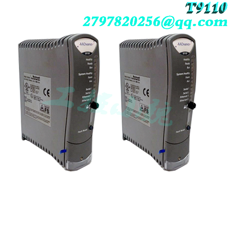
All High Integrity I/O Modules are made up of four sections: Host Interface Unit (HIU), the Field Interface Unit (FIU), the Field Termination Unit (FTU), and the Front Panel Unit (or FPU). Figure 2 shows a simplified block diagram of the Trusted 4-20 mA Analog Output Module. Processor firmware versions must be the same Multiple processors must contain the same version of firmware for synchronized operation. You can check the loaded firmware versions and download the latest versions if required using ControlFLASH (see the AADvance Configuration Guide for detailed procedures). 0 SNTP Changes made to the SNTP configuration do not become active until after a power cycle. 0 SOE Reference variables connected to SOE events are not reported by the OPC Portal Server. 0 Not recognizing Software Licenses Windows 64-bit versions of the operating software will not recognize Workbench soft (hard drive) licenses; Workbench licenses on USB dongles are recognized. These Tech Notes, Product Notices and Product Safety Advisories apply to this AADvance release: TN30006-01 Scan and throughput time TN30014- 01 Workbench communications may stall TN30017-01 No live data in Workbench simulator TN30020-01 CSV file import of REAL variables TN30025-01 Accuracy of SOE time stamps TN30027-01 Different data types in a FOR loop will halt a controller TN30032-01 Second resource set to 1 confuses debugging TN30033-01 Changing resource number of a controller leaves Flash files TN30036-01 Modify structure numbers corrupts attributes TN30037-01 Local variable wired to Analogue Output: custom shutdown setting in raw counts TN30039-01 Resizing columns causes Workbench to close TN30040-01 (503735) HMI Communication Performance TN30044-01 (509666) Wiring an element of a structured variable does not work TN30046-01 (515434) Online update not performed if changes are not applied TN30047-01 (543511) OPC Server 1.20.508 Installation Fix “Failed to get data for IDVersion”TN30049-01 (543513) Significant digits of decimal data in program constants and variable initial values TN30050-01 (543514) CURRENT_ ISA_ _DATE functions notsynchronized TN30051-01 (544046) Defective I/O Module prevents start up TN30052-01 (547008) Analogue Output Modules may default to 60s PST TN30054-01 (549387) Consumer tags lost through Archive and Restore PN2013-04-001 (539930/31) AADvance T9100 Processor Base Unit Over current 531022 Changing the address of a producer does not update the consumer variable that use that producer definition 549384 Saving the Hardware Link or Link Architecture Views forces recompilation 562451 AADvance discover will only allocate a gateway to the first port of each processor 549382 Multiple TCP Modbus slaves on the same processor must have unique port numbers
.jpg)
Application
There is no configuration required to the physical Output Module. All configurable characteristics of the Module are performed using tools on the Engineering Workstation (EWS) and become part of the application or System.INI file that is loaded into the TMR Processor. The TMR Processor automatically configures the Output Module after applications are downloaded and during an Active/Standby changeover. The IEC 61131 TOOLSET provides the main interface to configure the Output Module. Details of the configuration tools and configuration sequence are provided in Trusted Toolset Suite, publication ICSTT-RM249 (PD-T8082). There are three procedures necessary to configure the Output Module: 1. Define the necessary I/O variables for the field output data and Module status data using the Dictionary Editor of the IEC 61131 TOOLSET. 2. Create an I/O Module definition in the I/O Connection Editor for each I/O Module. The I/O Module definition defines physical information, for example, Chassis and Slot location, and allows variables to be connected to the I/O channels of the Module. 3. Using the Trusted System Configuration Manager, define custom LED indicator modes, per-channel default or fail-safe states, and other Module settings. The T8480 I/O Complex Equipment Definition includes eight I/O boards, referenced numerically by Rack number:There are two OEM parameters included in the first rack (AO Board). These OEM parameters define the primary Module position; declaring the Module’s chassis and slot location. There is no need to define the secondary Module position within the IEC 61131 TOOLSET. Where systems may be required to start up with Modules in the secondary position as the Active Module, for example, primary Module is not installed when application is started, the secondary Module’s position should be declared in the Module definition of the System Configuration Manager.(https://www.weikunfadacai1.com/)
Operation Status indicators on the Front Panel of the Module provide visual indications of the Module’s operational status and field output status. Each indicator is a bicolor LED. At the top and bottom of each Module is an ejector lever that is used to remove the Module from the Chassis. Limit switches detect the open/closed position of the ejector levers. The ejector levers are normally latched closed when the Module is firmly seated into the Controller or Expander Chassis.
Model recommendation:
ICS TRIPLEX T8903C

Reviews
There are no reviews yet.