
Description
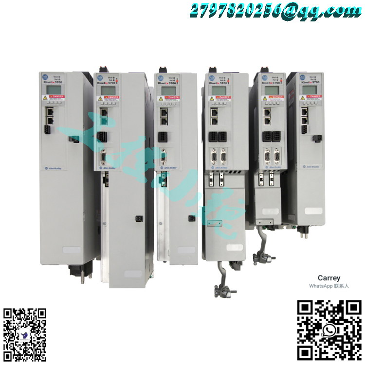
Product: Kinetix 51 00/5300 Digital Servo Drive and Accessories Manufacturer’s Name and Address: Authorized Representative’s Name and Address: Rockwell Automation Co., Ltd. Rockwell Automation 2014/35/EU Low Voltage Directive (Left Ventricle) April 30, 2012/EU EMC Directive. (electromagnetic compatibility) The 42nd Machinery Directive (Doctor of Medicine) in 2006 January 65, 2012/European Union RoHS Directive RoHS Regulation 2019/1781 (2009/125/EC) Ecological Design Directive (environmental protection) refers to the use of relevant harmonized standards or references and declaration of compliance: English: 61800-5-1:20071 Adjustable speed electric drive systems Part 5-1: Safety requirements – Electrical, thermal and energy. (Left ventricle) English: 61 800-3:2004+A1:2022 Adjustable speed electric drive systems Part 3: EMC requirements and specific testing methods (EMC) Adjustable speed electric drive systems Part 5-2: Safety servo drives, also known as “servo controllers” or “servo amplifiers”, are controllers used to control servo motors, which act similar to frequency converters acting on ordinary AC motors and are part of servo systems, Mainly used in high-precision positioning systems. Generally, servo motors are controlled through three methods: position, speed, and torque to achieve high-precision positioning of the transmission system. Currently, it is a high-end product in transmission technology.
Servo drives are applied in automation equipment such as industrial robots and CNC machining centers. In the servo drive speed closed-loop, the real-time speed measurement accuracy of the motor rotor is crucial for improving the dynamic and static characteristics of the speed control of the speed loop. To find a balance between measurement accuracy and system cost, incremental photoelectric encoders are generally used as speed sensors, and the corresponding commonly used speed measurement method is the M/T speed measurement method. Although the M/T speed measurement method has certain measurement accuracy and a wide measurement range, it has inherent drawbacks, mainly including: 1) at least one complete code disk pulse must be detected within the speed measurement cycle, which limits the minimum measurable speed; 2) The timer switches of the two control systems used for speed measurement are difficult to strictly maintain synchronization, and speed measurement accuracy cannot be guaranteed in measurement scenarios with significant speed changes. Therefore, the traditional speed loop design scheme using this speed measurement method is difficult to improve the speed following and control performance of the servo driver. The current mainstream servo drivers use digital signal processors (DSP) as the control core, which can achieve complex control algorithms, digitization, networking, and intelligence. Power devices generally use drive circuits designed with Intelligent Power Modules (IPM) as the core. IPM integrates drive circuits internally and has fault detection and protection circuits for overvoltage, overcurrent, overheating, undervoltage, etc. Soft start circuits are also added to the main circuit to reduce the impact of the startup process on the driver. The power driving unit first rectifies the input three-phase or mains power through a three-phase full bridge rectifier circuit to obtain the corresponding DC power. The rectified three-phase or mains power is then converted into a three-phase sine PWM voltage source inverter to drive a three-phase permanent magnet synchronous AC servo motor. The entire process of the power drive unit can be simply described as the process of AC-DC-AC. The main topology circuit of the rectifier unit (AC-DC) is a three-phase full bridge uncontrolled rectifier circuit. Basic requirements for servo feed system: 1. Wide speed range; 2. High positioning accuracy; 3. Sufficient transmission rigidity and high speed stability; 4. Quick response and no overshoot. In order to ensure productivity and processing quality, in addition to high positioning accuracy, good fast response characteristics are also required, that is, fast response to tracking command signals is required, as the CNC system requires acceleration during startup and braking The deceleration is large enough to shorten the transition process time of the feed system and reduce the contour transition error. 5. Low speed, high torque, and strong overload capacity. Generally speaking, servo drives have an overload capacity of 1.5 times or more within a few minutes or even half an hour, and can overload 4-6 times without damage in a short period of time. 6. High reliability requires the feed drive system of CNC machine tools to have high reliability, good working stability, strong adaptability to temperature, humidity, vibration and other environments, and strong anti-interference ability. Requirements for motors: 1. The motor can operate smoothly from the lowest speed to the highest speed, with minimal torque fluctuations, especially at low speeds such as 0.1r/min or lower, where there is still a stable speed without crawling. 2. The motor should have a large and long-term overload capacity to meet the requirements of low speed and high torque. Generally, DC servo motors require an overload of 4-6 times within a few minutes without damage. 3. In order to meet the requirements of fast response, the motor should have a small moment of inertia and a large locked rotor torque, as well as a time constant and starting voltage as small as possible.. 4. The motor should be able to withstand frequent starting, braking, and reverse rotation. Additional information: Authorized to prepare an authorized representative (see above). Technical Document (MD): Product Safety Function (MD): Safety Torque Off (STO, ERS): The difference between the three control methods. Generally, there are three control methods for servo: speed control, torque control, and position control. Both speed control and torque control are controlled using analog signals. Position control is controlled by sending pulses. The specific control method to be used depends on the customer’s requirements and the sports functions to be met. If you have no requirements for the speed or position of the motor, as long as you output a constant torque, of course, torque mode is used. If there are certain accuracy requirements for position and speed, but real-time torque is not very important, using torque mode is not very convenient, and using speed or position mode is better. If the upper controller has a good closed-loop control function, the speed control effect will be better. If the requirements themselves are not very high, or if there are basically no real-time requirements, using position control method does not have high requirements for the upper controller. In terms of the response speed of the servo driver, the torque mode has the smallest computational complexity and the driver has the fastest response to the control signal; The position mode has the highest computational complexity and the driver has the slowest response to control signals. When there is a high demand for dynamic performance in motion, it is necessary to adjust the motor in real-time. If the operation speed of the controller itself is very slow (such as PLC, or low-end motion controller), position control is used. If the operation speed of the controller is relatively fast, the position ring can be moved from the driver to the controller in the speed mode to reduce the workload of the driver and improve the efficiency (such as most middle and high-end motion controller); If there is a better upper controller, torque control can also be used to remove the speed loop from the driver. This is usually only possible with high-end dedicated controllers, and there is no need to use servo motors at this time. 1. Torque control: The torque control method is to set the output torque of the motor shaft externally through the input of external analog signals or the assignment of direct addresses. For example, if 10V corresponds to 5Nm, when the external analog signal is set to 5V, the motor shaft output is 2.5Nm. If the motor shaft load is lower than 2.5Nm, the motor rotates forward, and when the external load is equal to 2.5Nm, the motor does not rotate, When the torque is greater than 2.5Nm, the motor reverses (usually generated under gravity load). The set torque can be changed by instantly changing the setting of the analog quantity, or by changing the corresponding address value through communication. The application is mainly in winding and unwinding devices that have strict requirements for the force on the material, such as wire winding devices or fiber pulling equipment. The torque setting should be changed at any time according to the change of the winding radius to ensure that the force on the material will not change with the change of the winding radius. 2. Position control: The position control mode generally determines the rotational speed through the frequency of external input pulses, determines the rotation angle through the number of pulses, and some servo systems can directly assign values to speed and displacement through communication. Due to the strict control of speed and position, position mode is generally applied to positioning devices. Application fields such as CNC machine tools, printing machinery, etc.
3. Speed mode: Rotation speed can be controlled through analog input or pulse frequency. In the outer loop PID control with upper control device, the speed mode can also be positioned, but the position signal of the motor or the position signal of the direct load must be fed back to the upper control for calculation. The position mode also supports direct load outer ring detection of position signals. At this time, the encoder at the motor shaft end only detects the motor speed, and the position signal is provided by the direct final load end detection device. The advantage of this is that it can reduce errors in the intermediate transmission process and increase the positioning accuracy of the entire system.
The difference between servo and frequency converter
The technology of AC servo itself draws inspiration from and applies frequency conversion technology, which is achieved by imitating the control method of DC motors through frequency conversion PWM based on the servo control of DC motors. This means that AC servo motors inevitably have a frequency conversion process: frequency conversion is the process of rectifying 50 and 60Hz AC power into DC power, Then, various types of transistors (IGBT, IGCT, etc.) that can control the gate are used to invert the inverter into a frequency adjustable waveform similar to sine cosine pulsating current through carrier frequency and PWM regulation. Due to the frequency being adjustable, the speed of the AC motor can be adjusted (n=60f/p, n speed, f frequency, p pole number)
1.2.1 Frequency converter:
A simple frequency converter can only adjust the speed of the AC motor, and in this case, it can be opened or closed loop depending on the control method and frequency converter. This is the traditional V/F control method. Nowadays, many frequency converters have established mathematical models to convert the stator magnetic field UVW3 phase of AC motors into two current components that can control motor speed and torque. Most famous brand frequency converters that can control torque now use this method to control torque. The output of each phase of UVW needs to be equipped with a Hall effect current detection device, and after sampling and feedback, a closed-loop negative feedback current loop PID adjustment is formed; ABB’s frequency conversion has proposed a direct torque control technology that is different from this method. Please refer to relevant information for details. This can control both the speed and torque of the motor, and the speed control accuracy is better than v/f control. Encoder feedback can be added or not, and the control accuracy and response characteristics are much better when added.
1.2.2 Servo driver:
In terms of drivers: With the development of variable frequency technology, servo drivers have implemented more precise control techniques and algorithm calculations on the current loop, speed loop, and position loop (which are not available in frequency converters) inside the drivers. They are also much more powerful in terms of functionality than traditional frequency converters, and the main point is that they can achieve precise position control. The speed and position are controlled through the pulse sequence sent by the upper controller (although some servo systems integrate control units or directly set the position and speed parameters in the driver through bus communication). The algorithm, faster and more accurate calculations, and better performance electronic devices inside the driver make it superior to the frequency converter.
In terms of motors: The materials, structure, and processing technology of servo motors are much higher than those of AC motors driven by frequency converters (usually AC motors or various types of variable frequency motors such as constant torque and power). This means that when the driver outputs a power source with rapid changes in current, voltage, and frequency, the servo motor can generate responsive action changes based on changes in the power source. The response characteristics and overload resistance are much higher than those of AC motors driven by frequency converters, The serious difference in motor performance is also the fundamental reason for the difference between the two. That is to say, it is not that the frequency converter cannot output the power signal that changes so quickly, but that the motor itself cannot respond. Therefore, in the internal algorithm setting of the frequency converter, corresponding overload settings have been made to protect the motor. Of course, even if the output capacity of the frequency converter is not set, it is still limited. Some high-performance frequency converters can directly drive servo motors!!!
1.2.3 AC motor:
AC motors are generally divided into synchronous and asynchronous motors
1. AC synchronous motor: the rotor is made of permanent magnetic materials, so after rotation, with the change of the stator rotating magnetic field of the motor, the rotor also changes the speed of the response frequency, and the rotor speed=the stator speed, so it is called “synchronization”.
2. AC asynchronous motor: The rotor is composed of an induction coil and materials. After rotation, the stator generates a rotating magnetic field, the magnetic field cuts the induction coil of the stator, the rotor coil generates an induced current, and then the rotor generates an induced magnetic field. The induced magnetic field follows the change of the stator’s rotating magnetic field, but the change of the rotor’s magnetic field is always smaller than the change of the stator. Once it is equal to the same, the unchanged magnetic field cuts the induction coil of the rotor, and there is no induced current in the rotor coil, and the rotor’s magnetic field disappears, The rotor stalls and produces a speed difference with the stator, which then reacquires induced current… So a key parameter in AC asynchronous motors is the slip rate, which is the ratio of the speed difference between the rotor and stator.
3. Corresponding to AC synchronous and asynchronous motor frequency converters, there are synchronous and asynchronous frequency converters, and servo motors also have AC synchronous servo and AC asynchronous servo. Of course, AC asynchronous frequency conversion is common in frequency converters, while servo is common in AC synchronous servo.
4. Application
Due to the differences in performance and functionality between frequency converters and servo systems, their applications are not necessarily the same:
1. In situations where the requirements for speed control and torque control are not very high, frequency converters are generally used. There are also cases where position feedback signals are added to the upper position to form a closed loop and frequency converters are used for position control, resulting in low accuracy and response. Some frequency converters now accept pulse sequence signals to control speed, but it seems that they cannot directly control position.
2. In situations with strict position control requirements, servo can only be used for implementation. Additionally, the response speed of servo is much faster than that of frequency conversion. In some cases where precision and response requirements are high, servo control is also used. In almost all cases where motion can be controlled by frequency conversion, servo can be used instead. The key points are twofold: firstly, the price of servo is much higher than that of frequency conversion. Secondly, the reason for power is that the maximum frequency conversion can achieve several hundred KW or even higher, And the maximum servo power is tens of kilowatts. But with the continuous improvement of servo motor technology, the power can gradually reach several hundred kilowatts.
October 14, 2022 I. These products also comply with IEC 61800-5-1:2016 (excerpt) 2. These products also comply with IEC 61800-3:20173. These products also comply with IEC 61800-5-2:20164. These products also comply with IEC 62061:2005+A1:2012+42:2015 Document control number: 2198-CT027I-EN-E
Popular model recommendations:
2198-E1004-ERS
2198-E1007-ERS
21908-E1015-ERS
2198-E1020-ERS
2198-E2030-ERS
2198-E2055-ERS
2198-E2075-ERS –
2198-E2150-ERS
2198- E4004-ERS
2198-E4007-ERS
2198-E4015-ERS2198-E4020-ERS
2198-E4030-ERS
2198-E4055-ERS
2198-E4075-ERS –
2198-E4150-ERS
2198-GPFRM
2198-GPFRM3
2198-GPFRM4
2198-GPFRM5
2198-GPFRM6
2198-GPFRM7
2198-USBC
2198-USBF
2198-CONKIT-STO
2198-CONKIT-PKG
2198- TBIO
2198-KTBT
2198-K51CK-D15M
2198-C1004-ERS
2198-C1007-ERS
2198-C10I5-ERS
2198-C1020-ERS
2198-C2030-ERS
2198-C2055-ERS
2198-C2075-ERS
2198-C4004-ERS
2198-C4007-ERS
2198-C4015-ERS
2198-C4020-ERS

Reviews
There are no reviews yet.