Description
Many products have not been listed yet. For more products, please contact us
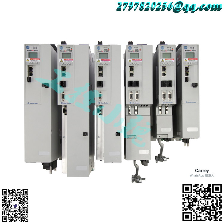
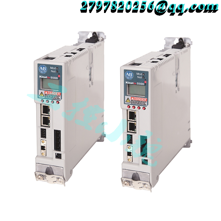
If the product model is inconsistent with the displayed image, the model shall prevail. Please contact us for specific product images, and we will arrange for photos to be taken and confirmed in the warehouse
We have 16 shared warehouses worldwide, so sometimes it may take several hours to accurately return to you. We apologize for any inconvenience caused. Of course, we will respond to your concerns as soon as possible.
The DC-bus link connector kits are required and comprised of these two components: • DC-bus links that are inserted between drive modules to extend the DC-bus from module-to-module. DC-bus links are included with inverter modules and the iTRAK power supply as indicated in the table below. • DC-bus end-caps are inserted into the first and last drive modules to cover the exposed DC-bus connector on both ends of the bus and are included with the DC-bus power supplies and regenerative bus supplies.https://www.weikunfadacai1.com/
(1) DC-bus links latch on both sides when inserted into the DC-bus connectors. To remove the DC-bus link, depress both sets of upper pivots to unlatch the lower pivots, hold the DC-bus link firmly, and pull upward.
24V Shared-bus Connector Kits 24V shared-bus connector kits are used to extend 24V control power from module-to-module. The 24V control power connection system is optional and mounted onto modules working from left to right. 24V shared-bus systems always start with a 24V DC input wiring connector followed by T-connectors and bus-bars. A 24V DC connection system is comprised of these three components: • The 24V input wiring connector that plugs into the DC-bus power supply or regenerative bus supply and receives input wiring for 24V DC (catalog numbers 2198-TCON-24VDCIN36 or 2198T-W25K-P-IN) • 24V DC T-connector that plugs into a module downstream and to the right of the 24V input wire connector or previous T-connector. • Bus bars that connect between a 24V input wiring connector and one or more T-connectors to extend the 24V control power from module to module.
System Mounting Toolkit
The 2198-K5700-MOUNTKIT system mounting toolkit is used to locate the drill-holes for your Kinetix 5700 drive system. Properly spaced drillholes are essential for engaging the zero-stack tab and cutout from module-to-module so that the DC-bus connectors are spaced properly and accept the DC-bus links. The Kinetix 5700 system mounting toolkit includes the drill-hole guide and mounting bar. Two M4 threadforming fasteners are also included. The mounting bar is mounted horizontally on the system panel. The drill-hole guide inserts behind the mounting bar and slides left and right. Holes and slots in the drill-hole guide let you establish the location of each Kinetix 5700 drive module. Kinetix 5700 System Mounting Toolkit

Control Power Current Specifications
Kinetix 5500 servo drives and the Bulletin 2198 capacitor module have different 24V DC power consumption. Factors to consider when calculating the combined current demand from your 24V DC power supply include the following: • Catalog number for each drive in the system • Whether servo motors include the holding brake option • Whether the system includes Bulletin 2198 capacitor modules (1 to 4 modules are possible)
Accessories – Kinetix 5500 Servo Drives
Kinetix 5500 drive accessories include the Bulletin 2198 capacitor module, shunt resistors, the encoder output module, AC line filters, and the shared-bus connection system. Kinetix 5500 servo drives are also compatible with Bulletin 2097 external shunt resistors.
Capacitor Module
The Kinetix 5500 capacitor module provides 1360 µF capacitance for applications where the Kinetix 5500 internal shunt module capacity is exceeded. The capacitor module can be used alone or in combination with a Bulletin 2097 external shunt module for applications with excessive regenerative energy. The Bulletin 2198-CAPMOD-1300 capacitor module is an option for Bulletin 2198 servo drive configurations with 200V or 400V-class operation. This section contains features, specifications, and product dimensions.
The shared-bus connection system is composed of three components: • Input wiring connectors that plug into the leftmost drive and receive input wiring for mains AC and 24V DC. • AC bus, DC bus, and 24V DC T-connectors that plug into the drives downstream from the first where AC, DC, and/or 24V control power is shared. DC bus T-connectors also plug into the first drive where DC-bus power is shared. • Bus bars that connect between drives to extend the mains AC bus, DC bus, and 24V DC control power from drive-to-drive.https://www.weikunfadacai1.com/
DSL Feedback Connector Kit
The Bulletin 2198-KITCON-DSL feedback connector kit is required for making feedback connections from Kinetix VP motors and actuators, and is included with each Kinetix 5500 servo drive. Motor power, brake, and the 2-wire feedback connections are made by using a single Bulletin 2090-CSxM1DF/DG cable. Refer to the Kinetix Motion Accessories Specifications Technical Data, publication KNX-TD004, for motor cable information.
Model recommendation:


Reviews
There are no reviews yet.