Description
Many products have not yet been launched, please contact us for more products
If the product model does not match the displayed image, the model shall prevail. Please contact us for specific product images, and we will arrange for photos to be taken in the warehouse for confirmation
We have 16 shared warehouses worldwide, so sometimes it may take several hours to accurately return to you. We apologize for any inconvenience caused. Of course, we will respond to your concerns as soon as possible.
DS200TCPSG1AEE Other names:
Input/output module DS200TCPSG1AEE
DS200TCPSG1AEE Controller module
Digital quantity module DS200TCPSG1AEE
Regarding DS200TCPSG1AEE
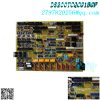
The DS200TCPSG1AEE printed circuit board product from General Electric is an important component of the Mark V series turbine control system and turbine control system components, as mentioned earlier. In the Mark V series driver components, this DS200TCPSG1AEE printed circuit board, or PCB for short, is specifically designed for critical core components. Although the functional description of the product as a power board may not be completely consistent with the TCPS function abbreviation of the product, this is an accurate manual description of the product. The DS200TCPSG1AEE printed circuit board is not an original power board manufactured for General Electric’s Mark V series; That will be the DS200TCPSG1 mother printed circuit board missing three important product revisions of the product.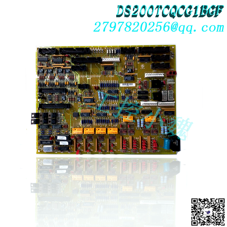
Hardware tips and specifications
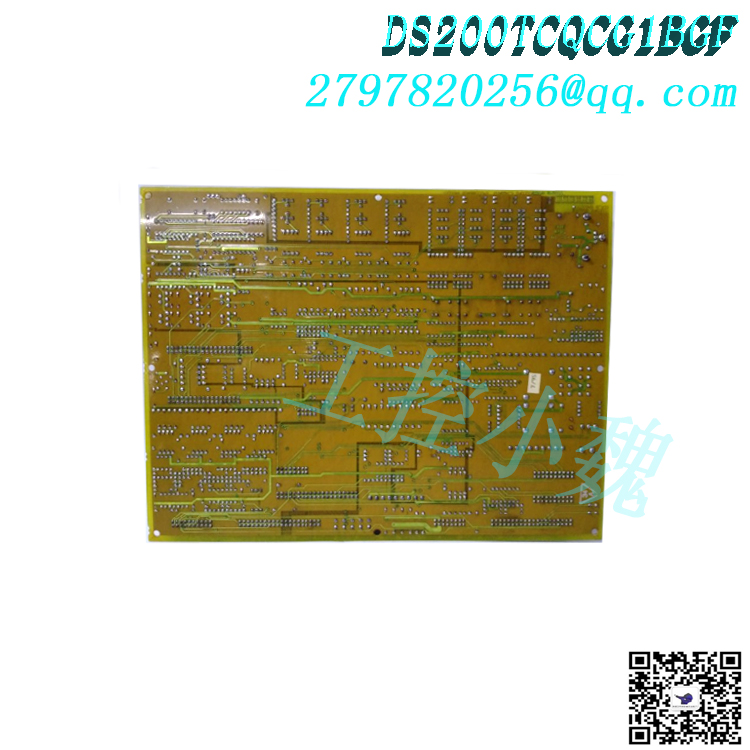
This DS200TCPSG1AEE power board integrates a series of necessary hardware components during its assembly process to achieve its functional status. The General Electric Power DC Input Board Model DS200TCPSG1AEE includes three fuses, a 16 pin connector, and a 9-pin connector. It also includes multiple testing points. The GE power DC input board DS200TCPSG1AEE is installed in the board cabinet of the driver. The cabinet design compatible with this Mark V series product includes a shelf with space to accommodate multiple boards. Each board should be fixed in place with screws and washers; According to GE, it is important to tighten the screws firmly, but not too tightly to prevent them from breaking or damaging the board. There are multiple test points on the DS200TCPSG1AEE printed circuit board for maintenance personnel to test the circuits on the board in case of problems. The test point is a bare metal pillar that enables the testing equipment to measure signals present in the circuit and activities occurring in the circuit. When you remove the circuit board from the rack to use test points or replace fuses, be sure to place the circuit board on an anti-static surface. Keep the anti-static bag when shipping the circuit board and always wear a wristband with the end of the wristband clipped onto the exposed metal surface to protect the surface voltage. This DS200TCPSG1AEE Mark V series printed circuit board uses a large number of connectors in its assembly, including: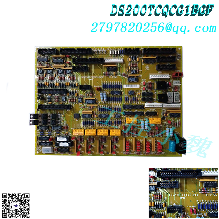
2PL power supply voltage connector
J1 125 V DC TCPS board connector
JC TCCA/TCQC board power voltage connector
JP1 AAHA/TCDA board power voltage connector
JP2 AAHA/TCDA board power voltage connector
X1 CCOM bus connector
All of these different connectors come with General Electric’s own shortened diagnostic labels and should receive some basic protection from the normal PCB coating of the printed circuit board, which coats each hardware element according to functional priority.
Frequently Asked Questions about DS200TCPSG1AEE
Are the three important product revisions of this DS200TCPSG1AEE power board considered backward compatible?
No. The three major revisions made to the DS200TCPSG1AEE PCB are not considered backward compatible, as only the first two of the three major revisions to the DS200TCPSG1AEE PCB are considered functional product revisions.
What types of components are included in this DS200TCPSG1AEE Mark V series product?
The DS200TCPSG1AEE power board has a normal Mark V series assembly style, as evidenced by the DS200 series label in the DS200TCPSG1AEE functional product number.
All products on this website are special products, and market prices have been fluctuating,
Please refer to the customer service quotation for details, as the product is new and the price is not genuine,
Please confirm the model, product, price, and other detailed information with customer service before placing an order. The website has been used,
The new one is for sale, please contact customer service for further communication.
Model recommendation:
DS200TCQCG1BBA
DS200TCQBG1B
DS200TBQCG1AAA
DS200TCQBG1BCA
DS200TCCBG3BED
DS200TCQAG1BHF-W01
DS200TCQAG1BHF-W01
DS200TCDAH1BHE
DS200TCQBG1BCB
DS200TCPSG1AEE
more……


-300x300.jpg)
-300x300.jpg)
admin –
This DS200TCPSG1AEE power board integrates a series of necessary hardware components during its assembly process to achieve its functional status. The General Electric Power DC Input Board Model DS200TCPSG1AEE includes three fuses, a 16 pin connector, and a 9-pin connector. It also includes multiple testing points. The GE power DC input board DS200TCPSG1AEE is installed in the board cabinet of the driver. The cabinet design compatible with this Mark V series product includes a shelf with space to accommodate multiple boards. Each board should be fixed in place with screws and washers; According to GE, it is important to tighten the screws firmly, but not too tightly to prevent them from breaking or damaging the board. There are multiple test points on the DS200TCPSG1AEE printed circuit board for maintenance personnel to test the circuits on the board in case of problems. The test point is a bare metal pillar that enables the testing equipment to measure signals present in the circuit and activities occurring in the circuit. When you remove the circuit board from the rack to use test points or replace fuses, be sure to place the circuit board on an anti-static surface. Keep the anti-static bag when shipping the circuit board and always wear a wristband with the end of the wristband clipped onto the exposed metal surface to protect the surface voltage.