Description
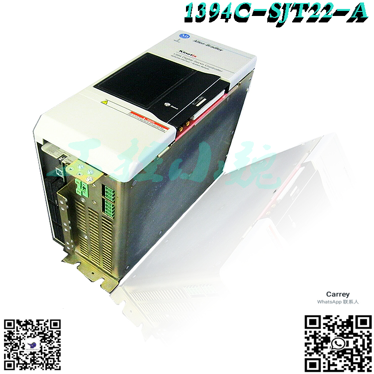
Description: The 1394C-SJT10-C-RL controller module is manufactured by Allen Bradley/Rockwell Automation and is used for applications in servo systems. It is a controller module in the 1394 series Allen Bradley servo controller and controller components. The rated power of the 1394C-SJT10-C-RL controller module is 10 kW. Its three-phase rated working voltage is 380 to 460 volts AC, and the rated frequency of this voltage is 50 to 60 Hz. The maximum short-circuit current rating of this controller module is 100000 amperes. The efficiency of the 1394C-SJT10-C-RL controller is 99%, with a continuous rated current of 14.7 amperes and a peak rated current of 29.5 amperes.
1394 system 1394 is a modular multi axis motion control and drive system family. Its unique design enables 1394 to be used as an integrated circuit motion controller and drive system (GMC), with Turbo or standard IMCTM S-class compact functions, integrated 9/440 CNC system, 9/series CNC digital interface drive system, SERCOS servo drive system or analog servo drive system. All 1394 systems have 360 and 480V three-phase input power, efficient IGBT power conversion, sliding and locking, and module to module connection systems. Each system module can be configured with four axis modules, and each axis module interfaces with the motor. 1394 provides significant panel space and interconnect savings. Series annotation: The C-series system module (catalog numbers 1394C-SJTx-x) and axis module (catalog numbers 1394C AMxx and – AMx IH), including functions, are not available on A-series and B-series modules (catalog numbers 1394-SJTxx-x and 1394 AMxx). Note: Only those familiar with 1394 should plan or implement installation, start-up, and subsequent maintenance systems for digital, communication, multi axis motion control systems, and related machinery. Failure to comply may result in personal injury and/or equipment damage. Attention: This product contains energy storage devices. To avoid the risk of electric shock, please wait for a few minutes after the power outage for five minutes or verify that all capacitors on the voltage have been discharged before attempting to repair, repair,
.jpg)
or remove this unit. You should only attempt the procedures in this manual if you are qualified to do so and are familiar with the control equipment and safety program publication NFPA 70E in solid-state. Note: The system integrator is responsible for applying local safety and electrical regulations. Attention: Improper application or installation of the driver may cause component damage or reduce the lifespan of the product. Wiring or application errors, such as motor size being too small, incorrect or insufficient AC supply, or driver failure due to high ambient temperature. Note: This drive contains ESD (electrostatic discharge) sensitive components and components. Static control precautions are required during installation, testing, maintenance, or repair. If ESD occurs, it may cause component damage and failure to comply with control procedures. If you are not familiar with static control programs, please refer to Allen Bradley’s publication 8000-4.5.2 “Prevention” or any other applicable ESD protection manual. General Motors System 1394 GMC system provides all functional compact motion controller and power conversion 1394 system modules of IMC S. Allen Bradley offers two 1394 version GMC system modules (standard GMC and GMC Turbo). Both systems are fully programmed and use GMLTM (Graphics Motion Control Language), providing Allen Bradley DH485, RS-232, and RS-422 as standard communication, and have remote I/O and AxisLink as communication options.
.jpg)
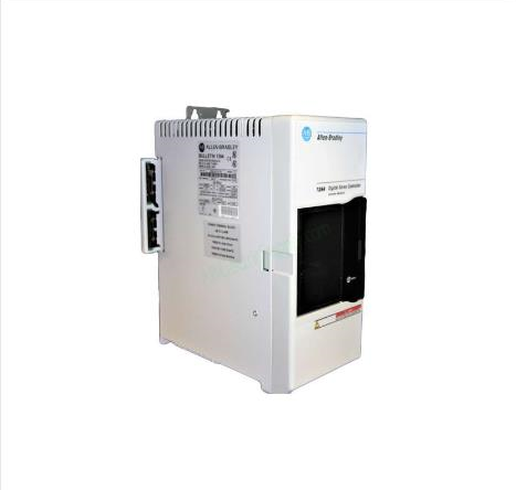
The 1394x-SJTxx-C (standard GMC) system supports four modules and provides four channels of auxiliary encoder input. This 1394C-SJTxx-L (standard GMC) is provided with 1394xSJTxx-C, but only supports one axis module and provides two auxiliary encoder input channels. In addition, 1394x-SJTx-T (GMC Turbo) provides more GML application memory and faster program execution. This 1394x-SJTxx-T provides 64K of memory and 32-bit processor, while the 1394x-SJTx-C provides 32K of 16 bit program memory. The 1394x-SJTxx-T also includes a direct high-speed link to SL to transfer data between 1394x-SJTxx-T and SLCTM. Figure 1. Two GMC Turbo systems (1394x-SJTxx-T) CNC interface systems 1394 9/series CNC interface systems (1394-SJTxx-E) provide digital servo systems for the 9/260 and 9/290 CNC systems.
This system provides all power electronic devices and uses cost-effective digital interface methods. The servo control of this system is controlled by a 9/series CNC. 1394 and the system fully interface with ODS, and use ODS for programming (offline development system) and CNC operation panel. Available options for Allen Bradley remote I/O, MMS/Ethernet (9/260 and 9/290 only), and data highway PlusTM (9/260 and 9/290 only) communication 9/series CNC interface systems. The SERCOS system 1394 SERCOS system module (1394C-SJTxx-D) provides a digital servo drive system with fiber optic digital network interface. It can be used as a speed or torque control system, and can be debugged using the Allen Bradley SERCOS interface module (announcement 1756 with 1756 MxxSE) for fast speed, providing automatic access to tuning and startup prompts. 1394 also provides the SCANportTM interface as a standard feature. For specific installation and wiring information, refer to the 1394SERCOS Multi Axis Motion Control System User Manual (publication 1394-5.20). The shaft module is connected to the system module using sliding and locking, and the module to module connection. For information on motors and cables, refer to 1326.AB 460%, Torque Plus series, AC servo motor product data (publication 1326A-2.9), 13264S series 460V, low inertia, brushless servo motor product data (publication 1326A-2.10), and 1326 460V AC servo motor cable product data (publication 1326A-2.11). In addition to the above equipment, you also need to provide the following information: ● three-phase input contactors ● 24V AC or DC logic power enable for three-phase input fuse system modules and connectors (only for analog servo)/DRIVEOK power supply (for all modules). For information on these topics, please refer to Appendix A. Note: The external shunt resistor kit (1394-SR 10A) can be used in 5 and 10kW systems, and its regenerative load exceeds the capacity of the internal 200W shunt resistor provided. A maximum of 5 and 10kW systems will not require a shunt resistor kit. All 22 products based on kW 1394 require external splitter modules (1394-SR9Ax or 1394-SR36Ax). This includes 1394 and
8520 catalog items. System module system module with rated power of 5, 10, and 22 kW (at 460V), accommodating the system control PCB and converting 360 V AC to 480 V AC, three phase, 50/60Hz input power to 530-680V DC link voltage. The 5 and 10kW system modules have an internal shunt resistor with a continuous rated power of 200W and a peak rated power of 40000W. The 22 kW system module requires an external splitter module. Search mode Search mode allows you to search for parameters that have already been established or modifiable links that are not at default values. The control status mode enables or disables HIM control and provides a fault and warning queue that lists the eight most recent fault occurrences. If the word “Trip” appears together with a fault, then the fault is actually a drive trip. To clear the queue, use the clear function. The password menu has three options. The password login menu is used to enable programming by entering the correct password. This default password is 0, which will disable password functionality. This password modification menu allows you to change your password. This password 1201 is permanently embedded in the system and can be used to overwrite the current password. Finally, the password logout menu is used to logout programming mode. Link parameter linking creates a connection between two parameters so that information can be passed to or from another device. The parameter is the parameter of the information source, and the destination parameter is the location where the information will be placed. For example, you can choose to link the axis parameter 220Vel to analog output 1 to provide an analog voltage to send a signal to the chart recorder. Note: When the system is running to link parameters, please perform the following steps: Note: These steps assume that you are from HIM (system waiting for bus). At HIM, press ENTER. A message similar to the following appears: Note: When the system is running to link parameters, please perform the following actions: Note: These steps assume that you are from HIM (system waiting for bus). At HIM, press ENTER. A message similar to the following appears: Select mode display 2. Press the up or down arrow keys until the following appears: Select mode link 3. Press the ENTER key. The system will record your selection and a message will appear with the following content: Link Settings Link
Popular model recommendations:

-100x100.jpg)
-100x100.jpg)

Reviews
There are no reviews yet.