-100x100.jpg)
-100x100.jpg)
-100x100.jpg)
Description
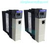
The Allen-Bradley 1756-OW16I is a ControlLogix Discrete output module that features Sixteen (16) Normally Open (N.O.), individually isolated contact outputs. Each contact output has a operating voltage range of 5-125VDC and 10-240VAC. It delivers output current ratings of 1 A @ 5-30VDC; 0.5 A @ 48VDC; 0.22 A @ 125VDC; 1.5 A @ 120VAC, 50/60 Hz and 0.75 A @ 240VAC, 50/60 Hz.
About 1756-OW16I
The Allen-Bradley 1756-OW16I is a Sixteen (16) channel discrete output module that is part of the ControlLogix automation platform. This module is a relay output module with contact form of Normally Open (N.O.) with individual isolation. This module may also be termed as a dry contact output module which is compatible to be operated at voltage ranges of 5-125VDC and 10-240VAC.
The 1756-OW16I delivers output current ratings of 1 A @ 5-30V DC; 0.5 A @ 48VDC; 0.22 A @ 125VDC; 1.5 A @ 120VAC, 50/60 Hz and 0.75 A @ 240VAC, 50/60 Hz. This module has a pilot duty rating of C300/R150.
Each output channel has a maximum output delay time of 10 ms for both signal transitions. It draws 150 mA current from the backplane @ 5.1 VDC and 24VDC with total backplane power draw of 4.4 Watts.Identify the Module Components You received the following components with your order: • ControlLogix isolated contact module • Removable terminal block (RTB) door label If you did not receive these components, contact your local distributor Rockwell Automation sales office. This module mounts in a 1756 chassis and uses a separately ordered RTB(a) to connect all field-side wiring. This module uses one of the following RTBs: • 1756-TBCH 36-position cage-clamp RTB • 1756-TBS6H 36-position spring-clamp RTB Use an extended-depth cover (1756-TBE) for applications with heavy gauge wiring or requiring additional routing space.
.jpg)
The 1756-OW16I has a maximum switching frequency of One (1) operation every Three (3) seconds or (0.3 Hz at rated load) with mean bounce time of 1.2 ms. Each of the output contacts are expected to operate up to 300 kHz when used with resistive loads and 100 kHz when used with inductive loads. Additionally, this module supports scheduled outputs and may be configured to Hold last state, On or Off during when FAULTED with Off as default setting. Similarly, output states may also be held at last state, with OFF as default setting during PROGRAM mode. This module is shipped with a Removable Terminal Block (RTB). Applicable RTB for use with this module are 1756-TBCH and 1756-TBS6H.Be sure that power is removed or the area is nonhazardous before proceeding. Repeated electrical arcing causes excessive wear to contacts on both the module and its mating connector. Worn contacts may create electrical resistance that can affect module operation. 1. Align the circuit board with the top and bottom chassis guidesKey the Module and Removable Terminal Block or Interface Module Use the wedge-shaped keying tabs and U-shaped keying bands to prevent connecting the wrong wires to your module. Key positions on the module that correspond to unkeyed positions on the RTB. For example, if you key the first position on the module, leave the first position on the RTB unkeyed.
.jpg)
.jpg)
The 1756-OW16I’s output delay time for both ON to OFF and OFF to ON is 10 milliseconds and it draws a backplane current of 150mA at both 5.1 Volts and 24 Volts DC and it has a total backplane power of 4.4 Watts. It has a thermal dissipation of 15.35 BTU/hour and dissipates 4.5 Watts at 60 degrees Celsius. Each output can accommodate a minimum current load of 10mA and a current leakage of 1.5 mA per point. The 1756-OW16I contact module has an initial contact impedance of 100 Ohms at 6V, 1A and it has a load-dependent switching frequency of 0.3 Hertz. It has a mean bounce time of 1.2 milliseconds with an expected contact life of 300 kHz resistive and of 100 kHz inductive. The 1756-OW16I has a scheduled output with a 16.7 second synchronization time with respect to Coordinated System Time (CST), and it has a circuit isolation voltage of 250 Volts with a basic insulation type tested at 1350 Volts AC for 2 seconds between outputs-to-backplane and output-to-output. The 1756-OW16I has a designated T4 North America temperature code and an open enclosure. Its operational temperature ranges between 0 and 60 degrees Celsius at a humidity of 5 to 95% without condensation.
FAQ for 1756-OW16I
What is this module’s power dissipation?
The 1756-OW16I has a power dissipation of around 4.5 Watts at a 60 degree Celsius temperature.
Can this module be purchased with a warranty?
Yes, the 1756-OW16I comes with a free one-year warranty from DO Supply, Inc.
What is this module’s operating voltage?
The 1756-OW16I can operate on 10 to 265 Volts of AC power or on 5 to 150 Volts of DC power.
Where can I send the 1756-OW16I to be repaired?
DO Supply, Inc. offers a variety of repair services for the 1756-OW16I.
What is the output contact form of the 1756-OW16I?
The 1756-OW16I has a Normally Open (N.O.) contact output.
Does the module come with individual isolation?
Yes. Each channel is individually isolated.
Does the 1756-OW16I come with internal fusing as well?
No. Internal fusing is not provided with this module.
Technical Description of 1756-OW16I
Allen Bradley ControlLogix Isolated Relay Output Module with 16-Point Individually Isolated Outputs
Model recommendation:
Reviews
There are no reviews yet.