Description
The Allen-Bradley 150-B97NBDB solid-state controller belongs to the Bulletin 150 SMC Dialog Plus series of motor controllers that support a voltage range of 200 to 600 Volts AC and that offer 1 to 1000 Amps of current at the output. The SMC Dialog Plus controllers are certified by the CSA, CE, and CCC standards and they also comply with the UL 508, EN/IEC 60947-1, and CSA C22.2 standards. The 150-B97NBDB controller is a 97 Amps rated motor controller with an open enclosure. The pump control is an optional motor control feature which is available as a standard feature on the 150-B97NBDB controller. Several other motor control options can be ordered from Allen-Bradley, including the preset slow speed and the accu stop. A total of six motor control modes are available on all SMC Dialog Plus controllers, including the current limit, dual ramp start, and energy saver modes.
The output power range for the 150-B97NBDB controller is 5 to 500 Horsepower at 460 Volts AC. The controller can operate over a range of input voltages from 200 Volts AC to 460 Volts AC. Only three-phase input at 50 to 60 Hertz line frequency is supported. The control voltage range is 100 to 240 Volts AC. A 350 Amps rated fuse can be used with the controller for the purpose of providing short circuit protection. The maximum heat dissipation rating is 285 Watts. The approximate shipping weight of the 150-B97NBDB controller is 23 pounds and the dimensions of the controller are 12 x 9.77 x 10.09 inches. The working temperature range for the controller is from 0 to 50 degrees Celsius.
.jpg)
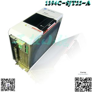
The 1391-DES45-DI-AQB is a Digital Servo drive that is microprocessor based primarily used with Allen-Bradley’s 1326 Servo motor. This servo drive is designed in compact form however, this drive supports add-on components that is part of the drive’s scalability feature.(https://www.weikunfadacai1.com/)
Main featured of the 1391-DES45-DI-AQB include an integrated display that is used for local configuration of the servo drive’s parameters. It also has an Encoder output with optional selections including 2048, 1024, 512 and 256 pulses per motor revolution. Higher pulses provide higher resolution and higher feedback accuracy.
The front panel of this servo drive display the Human Interface Module (HIM) with Five (5) digital keypad to allow navigation and modification of the drive’s parameters. It also has an integral status LED that flashes green when no fault is detected and low bus voltage; Steady Green when no fault and bus voltage is at the right level; Flashes Red when a drive fault has occurred. It also has an Enable LED which is steady green when enable input is closed. When the enable input is open, the enable LED is not illuminated.
The TB2 and TB3 interface terminals are located at the bottom of the servo drive. TB2 is used for interfacing external signal while TB3 is utilized to terminate encoder output signals. Integrated fuses and circuit breaker as well as TB4, TB5 and duty cycle selector switch are situated on top of the drive. Though this drive has internal protection circuitry, external protection is recommended for installation. If using an isolation transformer, Allen-Bradley recommended appropriate 1391 Isolation transformers as the use of 3rd party transformer will void the UL listing of the equipment.
The Allen-Bradley 1391-DES45-DI-AQB is a digital and programmable single-axis pulse-width modulated AC servo drive. The 1391-DES series of drives are designed to control the speed and torque of an AC servomotor at 33-50% more than their rated speed. The 1391-DES45-DI-AQB is designed for an input power rated at 230V AC (3-phase), with frequency of 50-60 Hz. The 1391-DES45-DI-AQB is equipped with a cooling fan which is rated at 50 CFM (unloaded). Its nominal bus voltage is 300V DC and its continuous current is 45A RMS with a peak current going up to 90A RMS. The continuous power output is rated at 15 kW with a peak power output going up to 30 kW. The encoder output can be varied as required to provide 2048/1024/512/256 pulses/motor revolution. The 1391-DES45-DI-AQB includes an integrated 2-line, 16-character LCD screen and a 5-button keypad for programming. To prevent any damage, the drive should be mounted in an enclosure that is clean, dry and ventilated by cooled and filtered air. Enclosures that are vented with ambient air must have the appropriate filtering to protect the 1391-DES45-DI-AQB against contamination from oils, coolants, dust, and condensation. The operating temperature range is 32 to 40 Deg. Fahrenheit and 5-95% relative humidity (non-condensing). The power dissipated during operation varies with the load: at 20% it is 104 W, at 40% it is 208 W, at 60% it is 312 W, at 80% it is 416 W and at 100% it is 520 W. An integrated 3-pole magnetic circuit breaker protects the DC bus supply, input rectifier, and power circuitry against overcurrent. The dimensions of the drive are 482.6 x 157.5 x 293.6 mm and it weighs 15.4 kg.
.jpg)
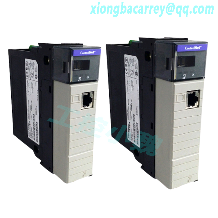
The 1336-L5 is a Control Interface option card that is part of the 1336 Plus Adjustable Frequency AC Drive by Allen-Bradley. It is specifically compatible for use with the 1336 Plus, 1336 Force, and 1336 Impact, drives specifically, Frame A-H drives except Frame C drives with 25 HP and 30 HP power rating. This control interface board is mounted at the bottom of the main control board, sitting atop the TB2 terminal strip. The 1336-L5 is a 24 VDC / 24 VAC logic board that is used to receive additional external contact closure signals. These signals could be any circuit that provides High = True logic state such as hardwired circuits, Programmable Logic Controller (PLC) output modules, auxiliary contacts, sequencers, and similar circuitry that delivers 24 VDC / VAC rated signal voltage. The 1366-L5 has Twelve (12) screw-type terminals that are designed to be terminated with wire sizes 2.1 and 0.30 mm2 (14 and 22 AWG) copper wires. Tighten connections at Torque of 0.90-1.13 N-m (8-10 lb.-in.). Terminal 19 and 20 are intended for Start / Stop functions only with terminal 19 programmable to accept Status, Run, Forward, and Start input while terminal 20 is configurable to Stop / Fault Reset signals. Other inputs that can be wired to the TB3 terminal strip available to the control interface board include Reverse / Forward; Jog; Auxiliary and Speed Select 1-3 inputs. This interface board supports 2-wire and 3wire control wiring configurations. Other commands that can be initiated via the control interface board are Acceleration, Deceleration, Sync, and Traverse.
The Allen-Bradley 1336-L5 +24 Volts AC/DC Control Interface Board is a logic control interface option board for the 1336 adjustable frequency AC drives, which provides a means of interfacing various drive commands and functions. This board, like all other logic interface boards, is located on Port A of the main control board, and it has 9 control inputs, which can be programmed for any selected function. To function properly, the 1336-L5 logic control interface board requires a circuit capable of operating at high = true logic, and it requires 24 Volts AC/DC user-supplied voltage to function. This board also functions properly with a circuit capable of generating no more than 8 Volts DC/10 Volt AC and 1.5/2.5 mA in the low state, and a voltage range of +20 to +26 Volts AC, with a source current of 10 mA for each input in the high state. The 1336-L5 can be used to program various drive commands and functions, and among those functions are 2 drive accel/decel control inputs which allow users to select the acceleration and deceleration times the drive uses. The 1336-L5 can also be used for local control, which gives users exclusive control of the drive logic, and it also helps control the Fwd/Reverse function, which controls reverse and forward direction operation. This board can also be used to control other various drive functions like the Enable, Flux Enable, Jog, Digital Potentiometer, Ramp, Reset, and Start functions. The 1336-L5 is installed on the main control board at pins 2 and 3, and 17 and 18 of the J1 jumper on the main control board, and it is compatible with the 1771-OB, -OQ, -OBB, -OBD, -OBN, and -OQ16 PLC modules.
.jpg)
FAQ for 1336-L5
1. What is the recommended wire size used when terminating signals to the 1366-L5?
Recommended wire size range is 2.1 and 0.30 mm2 (14 and 22 AWG) copper wires.
2. What are the 1336 drives that support the installation of 1366-L5?
Compatible drives are Frame A-H drives of 1336 Plus, 1336 Force, and 1336 Impact.
3. What is the terminal strip hosted by the 1336-L5?
The 1336-L5 hosts the TB3 terminal strip.
Technical Description of 1391-DES45-DI-AQB
Allen-Bradley Control Interface with 24V AC/DC Input Voltage
The Allen-Bradley 1391-DES45-DI-AQB has a Integral Display User Interface, a Quad Encoder Output Output Configuration, and a 115V AC M Contactor Coil Voltage. It also contains a 300V DC Nominal Bus Output Voltage and a 45A Continuous Current (RMS).
Model recommendation:
Reviews
There are no reviews yet.