-100x100.jpg)
-100x100.jpg)
-100x100.jpg)
Description
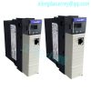
2.1 System Overview The SST-PFB-SLC is the ProfiBus scanner for the SLC 500. It enables communication between a SLC processor (SLC 5/03 or later) and DP remote I/O devices on a ProfiBus network. It acts as a ProfiBus DP remote I/O scanner to scan up to 96 slaves. The scanner supports up to 244 bytes of input data and 244 bytes of output data per slave. If you use the SST ProfiBus Configuration Tool to configure the scanner, you can have up to 1000 words of input data and 1000 words of output data. If you use Siemens COM PROFIBUS to configure the scanner, it supports up to 160 words of input data and 160 words of output data in total. The scanner can reside in any slot in the local SLC chassis except slot 0 (reserved for the SLC processor). You can have multiple scanners in the same rack. The scanner supports all standard ProfiBus baud rates (9600, 19200, 93.75k, 187.5k, 500k, 750k, 1.5M, 3M, 6M, 12M) You configure the I/O on the DP network using either the SST ProfiBus Configuration Tool or Siemens COM PROFIBUS configuration software. The SST configuration tool exports the configuration to a *.bss file (binary), while COM PROFIBUS exports the configuration to a
.2bf file (binary). You upload the configuration to the scanner via the serial port on the scanner, using an Xmodem transfer from any serial communications software. The scanner stores this configuration in flash memory on the scanner so you don’t need to upload the configuration every time you start the SLC. The input and output data for the slaves is mapped into SLC I, O, M0 and M1 files. The mapping depends on the addresses you assign in the configuration you create with either configuration tool. The scanner does not require setting up a G file in the SLC. All the configuration is done with the SST configuration tool or COM PROFIBUS. The scanner maintains the following status information about the network and the I/O modules on the network: • slave status for each slave • network diagnostic counters • DP master diagnostic counters • FDL diagnostic countersThe SLC processor scan and the scanner I/O scan are independent (asynchronous) of each other. The SLC processor reads the scanner input data during its input scan and writes the output data during its output scan.
.jpg)
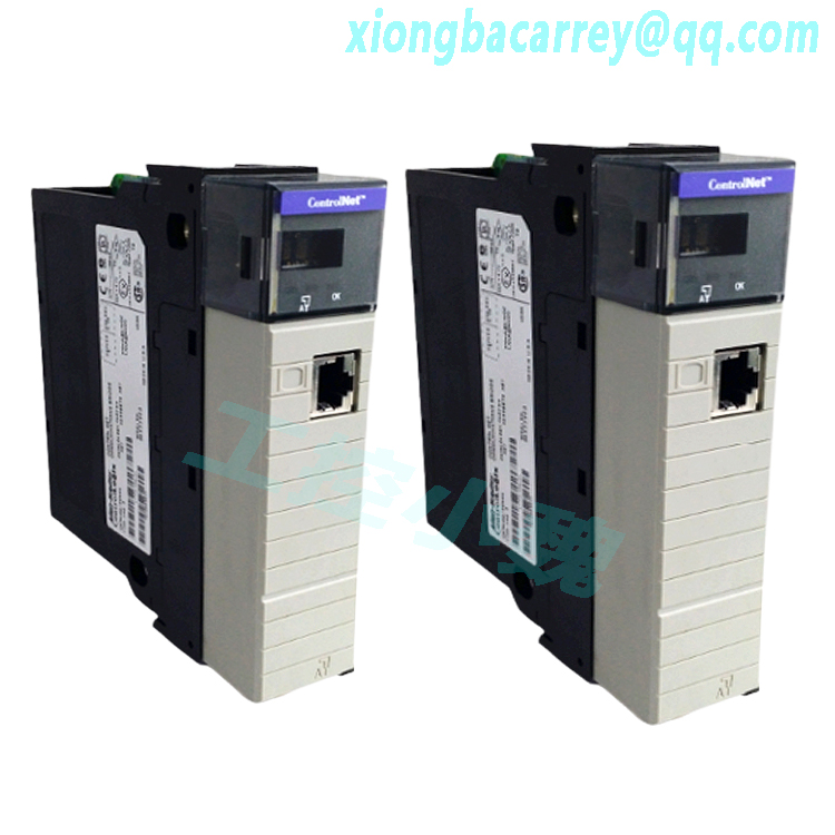
2.2.1 LEDs There are two LEDs on the scanner, the SYS LED and the COMM LED. The SYS LED indicates overall status of scanner operations. The COMM LED indicates communication status. Refer to section 4.3, Status LEDs, in this manual for more detailed information. 2.2.2 9-pin ProfiBus connector The 9-pin ProfiBus connector connects the scanner to the ProfiBus network. 2.2.3 Configuration port Use the configuration port to upload I/O configurations exported from the SST ProfiBus Configuration Tool or Siemens COM PROFIBUS to the scanner.
.jpg)
3.4.2 Getting the Scanner Running 1. Install the SST ProfiBus Configuration Tool. Run the setup.exe file from the Windows 32 distribution disk. 1. Create your I/O configuration. Refer to section 5.2, Creating an I/O Configuration in the SST ProfiBus Configuration Tool, in this manual for more detailed information. 2. Create a new file. 3. Select the master station number. 4. Configure the bus parameters and set the network baud rate. 5. Configure the slave parameters for each slave, set the slave station number, the slave module type and assign I/O addresses to the slave. 6. Save the file, then export the configuration to a binary file (.bss). 7. Connect your communication software to the scanner using a null modem cable. While the SLC is in program mode, send an asterisk (*) to the scanner using your terminal software. You may need to send several “*”s as the scanner auto baud detects. See section 5.4 for details. Note The I/O addresses determine where the slave data maps into the SLC data table. Siemens inputs P0 to P63 map into I0 to I31. Siemens outputs P0 to P63 map into O0 to O31.
4.1.1 Installation 1. Disconnect power. 2. Align the full-sized circuit board with the chassis card guides. The first slot (slot 0) of the first rack is reserved for the SLC 500 processor. 3. Slide the module into the chassis until the top and bottom latches catch. 4. Attach the ProfiBus cable. Turn on termination as required (Is this station at one of the two physical ends of the network?). 5. Route the cable down and away from the scanner. 6. Cover all unused slots with the card slot filler, Allen-Bradley catalog number 1746-N2. 4.1.2 Removal 1. Disconnect power. 2. Remove all cabling from the scanner. 3. Press the releases at the top and bottom of the module and slide the module out of the module slot. 4. Cover all unused slots with the card slot filler, Allen-Bradley catalog number 1746-N2.
.jpg)
The two physical ends of the network should be terminated. There should be two, and only two, terminators on a network. The recommended cable is Beldon3079A. Examples include: • Siemens 6XV1 830-OAH10 Two Core shielded • Siemens 6XV1 830-OBH10 w/PE Sheath • Siemens 6XV1 830-3AH10 for underground burial • Siemens 6XV1 830-3BH10 trailing cable • Bosch Comnet DP #913 548 Flexible ProfiBus cable • Bosch Comnet DP #917 201 Trailing ProfiBus Cable • Bosch Comnet DP #917 202 Massive ProfiBus Cable Allen Bradley blue hose which has an impedance of 78 ohms, is not recommended
Connect to the serial port using any communication software such as Windows Terminal or Hyperterminal. The scanner serial port supports any baud rate from 9600 baud to 115 kbaud, with no parity, 8 data bits, 1 stop bit. The scanner automatically detects the baud rate you are using by adjusting the baud rate until it receives an “*”. 4.3 Status LEDs 4.3.1 SYS LED If you are using the scanner as a DP master and a DP slave, the SYS LED shows the status of both operations sequentially. The master status is flashed first, followed by the slave status. If you are using the scanner for FDL the sequence is DP Master DP slave FDL messages and FDL SAPs. The following table provides a description of the LEDs:
5.1.2 PLC-500 Ladder Logistics This procedure was tested with version 8.15 of PLC-500 Ladder Logistics. If you are using a previous version, contact SST for the proper procedures. 1. Create a new program offline. 2. Select the SLC processor, memory, and operating system. 3. Select the rack number for the scanner (rack 1) and the rack size. 4. Select the slot in which the SST-PFB-SLC is located, and press F5 Select to configure the scanner 5. Select Other and enter the scanner ID code (13635). 6. Select spioCfg. 7. Press F1 M0 length and set the M0 file size to 4200 8. Press F2 M1 length and set the M1 file size to 4200. 9. If you are using fewer than 32 input words or 32 output words, you can change the scanned input and output words. 10. You do not have to set the G file size or set an iSr number. 11. Press Esc to exit spioCfg. 12. Press Esc again to create the files. 13. Create the rest of your control program. 14. Exit the programming software and save the configuration and the program. 15. Transfer the program to the SLC.
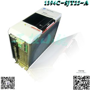
Model recommendation:
Reviews
There are no reviews yet.