-100x100.jpg)
-100x100.jpg)
-100x100.jpg)
Description
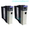
The 1756-DHRIO is an Allen-Bradley communication module that support Remote I/O and Data Highway Plus (DH) protocol. This module has embedded Two (2) ports for Channel A and B each with a with 3-Pin terminal for wiring Data Highway Plus (DH+) or Remote I/O (RIO) and a single 8-Pin mini-DIN port that is connected parallel to Channel A.The Allen-Bradley 1756-DHRIO is a ControlLogix Data Highway Plus/Remote I/O communication interface module. This module has Two (2) channels, supporting communication rates of 57.6 kilobytes per second, 115.2 kilobytes per second, and 230.4 kilobytes per second, depending on the cable length. It can transfer a message through a maximum of three chassis and four communication networks. With this module, information exchange can be done among devices such as PLCs, SLCs, and ControlLogix controllers, even on different networks.(http://www.weikunfadacai1.com)
.jpg)
It supports the following types of communication: Remote I/O, Control and Information Protocol (CIP) Messaging, and Data Highway Plus (DH+) Messaging between devices. It can have up to 32 Logix connections and the remote I/O link can connect to a remote I/O device, as well as other intelligent devices. When connected to a remote I/O network, it can act as an adapter or scanner and transfer analog, digital, block, and specialty data even with the absence of message instructions. Prior to installing the 1756-DHRIO module, you need to program the network type switches for each channel and install and connect a ControlLogix power supply and chassis. You can install as many modules as you can in the same chassis but this will depend on your available power supply. Note that modules can also be installed or removed even when the chassis power is applied but you need to observe safety precautions, particularly that the area is nonhazardous and power is removed, to prevent an electrical arc that can cause excessive wear to the contacts of both the module and the connector. Make sure to discharge potential static because the module is sensitive to electrostatic discharge.The Data Highway Plus/RIO module supports the following types of communication:
.jpg)
.jpg)
RIO and DH+ protocol uses the same cable type. Recommended cables are Belden 89463 twinaxial, 0.52 mm² (20 AWG) rated at 200 °C (392 °F). Applicable spare connector is Phoenix terminal with part number MVSTBR2.5/3-ST BK AU.Link Design When you design your DH+ link, use good design practices, including laying out the link before installation. We also recommend you consider the following when designing your DH+ link: • All performance requirements • Maintenance • Possible future changes to the link Use a1770-CD (Belden 9463) cable to connect your 1756-DHRIO module to DH+. Use a Belden 89463 cable to connect your 1756-DHRIOXT module to DH+. Connect a DH+ network by using a daisy chain or trunk line/drop line configuration. Trunk Line/Drop Line Considerations When using a trunk line/drop line configuration, use 1770-SC station connectors and follow these cable-length guidelines: • trunk line-cable length – depends on the communication rate of the link • drop-cable length – 30.4 m (100 cable-ft.) Verify that your system’s design plans specify cable lengths within allowable measurements.Application Guidelines Consider the following application guidelines when configuring a DH+ link for your system: • Minimize the number of DH+ nodes to achieve acceptable response times. Keep in mind the size and frequency of messages exchanged between devices. • Limit the number of stations on your network when you are trying to achieve the fastest control response time. Establish separate DH+ networks to bring-on additional stations. • Do not add or remove stations from the network during machine or process operation. If the network token resides with a device that is removed, the token can be lost to the rest of the network. The network is automatically reestablished, but it could take several seconds. Control is unreliable or interrupted during this time. • When possible, do not program controllers online during machine or process operation. This could result in long bursts of DH+ activity, increasing response time. • When possible, add a separate DH+ link for programming processors to keep effects of the programming terminal from the process DH+ link.
DH+ and Remote I/O network requires the use of a terminating resistor as it follows daisy-chain topology. This resistor is installed at the first and last node of the network. Resistor values depend on the network speed. 82 Ohms is used for network speed of 230.4Kbps. 150 Ohms is used for network speed of 57.6 Kbps or 115.2 Kbps. Other considerations are also considered including the type of devices connected to the network. The terminating resistor is installed across line 1 and line 2 of the cable. The 3rd cable is the shield cable.Sending Local DH+ Messages on DH+ If a 1756-DHRIO channel receives a DH+ message with a destination link ID=0 from a ControlLogix controller in the same chassis, the module sends the message as a local DH+ message. Limitations of Local DH+ Messaging When using Local DH+ Messaging, you must remember: • The DH+ message contains only a node ID for a node on the DH+ network. • A local DH+ message sent to the node ID of a port on the 1756-DHRIO and 1756-DHRIOXT modules is forwarded to one user-configured controller slot. • Messages on one DH+ network cannot be routed to other networks. Routing Error in Local DH+ Messaging If the module has a problem with routing a DH+ message, it can return a response with an error status of D0 hex. A PLC-5 displays this error as D000 hex when monitoring the message instruction. If you receive this error message, perform the following actions: • Check your message instruction to make sure a destination node was entered. • Check your default slot configuration to make sure that it matches the location of the ControlLogix controller in the chassis. • Make sure power is applied to the module. Programming Message Block Instructions in a Controller for Local DH+ Messaging Before programming your message block instructions in your controller, you must: • Determine which links send and receive DH+ Local messages. • Draw a network to make sure you meet the design requirements for Local DH+ messages.
To terminate the cable following RIO protocol, Line 1 is connected to the bottom pin or terminal 1, shield cable is terminated to the middle pin and Line 2 is terminated to the last pin. To wire the cable appropriately as DH+ protocol, simply reverse the connection of Line 1 and Line 2.
This module supports communication with Flex IO, POINT IO systems and messaging functions with PLC 5, SLC, CompactLogix and ControlLogix controllers as well.
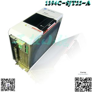
Recommended inventory module models:
Reviews
There are no reviews yet.