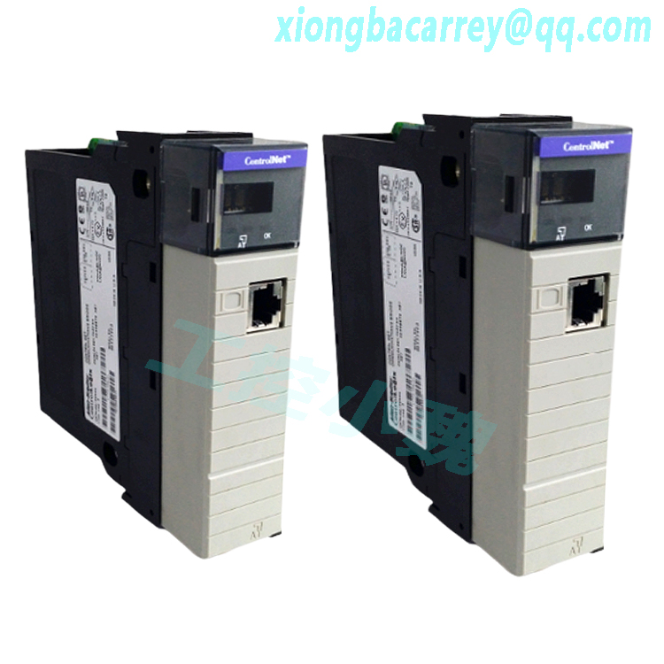
Description
Module Description The 1769-OW16 is a 16 point relay output module that can control AC or DC loads. The module has 2 isolated groups of 8 points each. This allows you to mix both AC and DC loads on one module.Module Installation Compact I/O is suitable for use in an industrial environment when installed in accordance with these instructions. Specifically, this equipment is intended for use in clean, dry environments (Pollution degree 2(1)) and to circuits not exceeding Over Voltage Category II(2) (IEC 60664-1).(3) System Assembly The module can be attached to the controller or an adjacent I/O module before or after mounting. For mounting instructions, see “Panel Mounting” on page 5, or “DIN Rail Mounting” on page 7. To work with a system that is already mounted, see “Replacing a Single Module within a System” on page 7. The following procedure shows you how to assemble the Compact I/O system. 1. Disconnect power. 2. Check that the bus lever of the module to be installed is in the unlocked (fully right) position. 3. Use the upper and lower tongue-and-groove slots (1) to secure the modules together (or to a controller). 4. Move the module back along the tongue-and-groove slots until the bus connectors (2) line up with each other. 5. Push the bus lever back slightly to clear the positioning tab (3). Use your fingers or a small screw driver. 6. To allow communication between the controller and module, move the bus lever fully to the left (4) until it clicks. Ensure it is locked firmly in place.

Panel Mounting Using the Dimensional Template Locate holes every 17.5 mm (0.689 in.) to allow for a mix of single-wide and one-and-a-half-wide modules (e.g. 1769-OA16). Panel Mounting Procedure Using Modules as a Template The following procedure allows you to use the assembled modules as a template for drilling holes in the panel. If you have sophisticated panel mounting equipment, you can use the dimensional template provided on page 6. Due to module mounting hole tolerance, it is important to follow these procedures: 1. On a clean work surface, assemble no more than three modules. 2. Using the assembled modules as a template, carefully mark the center of all module-mounting holes on the panel. 3. Return the assembled modules to the clean work surface, including any previously mounted modules. 4. Drill and tap the mounting holes for the recommended M4 or #8 screw. 5. Place the modules back on the panel, and check for proper hole alignment. 6. Attach the modules to the panel using the mounting screws. 7. Repeat steps 1 to 6 for any remaining modules. TIP If mounting more modules, mount only the last one of this group and put the others aside. This reduces remounting time during drilling and tapping of the next group.
.jpg)
DIN Rail Mounting The module can be mounted using the following DIN rails: 35 x 7.5 mm (EN 50 022 – 35 x 7.5) or 35 x 15 mm (EN 50 022 – 35 x 15). Before mounting the module on a DIN rail, close the DIN rail latches. Press the DIN rail mounting area of the module against the DIN rail. The latches will momentarily open and lock into place. Replacing a Single Module within a System The module can be replaced while the system is mounted to a panel (or DIN rail). 1. Remove power. See attention note on page 3. 2. On the module to be removed, remove the upper and lower mounting screws from the module (or open the DIN latches using a flat-blade or phillips style screw driver). 3. Move the bus lever to the right to disconnect (unlock) the bus. 4. On the right-side adjacent module, move its bus lever to the right (unlock) to disconnect it from the module to be removed. 5. Gently slide the disconnected module forward. If you feel excessive resistance, check that the module has been disconnected from the bus, and that both mounting screws have been removed (or DIN latches opened). 6. Before installing the replacement module, be sure that the bus lever on the module to be installed, and on the right-side adjacent module are in the unlocked (fully right) position. 7. Slide the replacement module into the open slot. 8. Connect the modules together by locking (fully left) the bus levers on the replacement module and the right-side adjacent module. 9. Replace the mounting screws (or snap the module onto the DIN rail).
.jpg)
Field Wiring Connections Grounding the Module This product is intended to be mounted to a well-grounded mounting surface such as a metal panel. Additional grounding connections from the module’s mounting tabs or DIN rail (if used), are not required unless the mounting surface cannot be grounded. Refer to Industrial Automation Wiring and Grounding Guidelines, Allen-Bradley publication 1770-4.1, for additional information.
A removable, write-on label, (see page 2, item 9) is provided with the module. Remove the label from the door, mark the identification of each terminal with permanent ink, and slide the label back into the door. Your markings (ID tag) will be visible when the module door is closed. Removing the Finger-Safe Terminal Block When wiring field devices to the module, it is not necessary to remove the terminal block. If you remove the terminal block, use the write-on label on the side of the terminal block to identify the module slot location and type. To remove the terminal block, loosen the upper and lower retaining screws. The terminal block will back away from the module as you remove the screws. When replacing the terminal block, torque the retaining screws to 0.46 Nm (4.1 in-lbs). Wiring the Finger-Safe Terminal Block When wiring the terminal block, keep the finger-safe cover in place. 1. Loosen the terminal screws to be wired. SLOT _____ MODULE TYPE ______ wiring the finger-safe terminal block upper retaining screw lower retaining screw 10 Compact™ 16-Point AC/D
Route the wire under the terminal pressure plate. You can use the bare wire or a spade lug. The terminals will accept a 6.35 mm (0.25 in.) spade lug. 3. Tighten the terminal screw making sure the pressure plate secures the wire. Recommended torque when tightening terminal screws is 0.68 Nm (6 in-lbs). Simplified Output Circuit Diagram Wire Size and Terminal Screw Torque Each terminal accepts up to two wires with the following restrictions: TIP The terminal screws are non-captive. Therefore, it is possible to use a ring lug [maximum 1/4 inch o.d. with a 0.139 inch minimum i.d. (M3.5)] with the module. TIP If you need to remove the finger-safe cover, insert a screw driver into one of the square, wiring holes and gently pry the cover off. If you wire the terminal block with the finger-safe cover removed, you will not be able to put it back on the terminal block because the wires will be in the way

Output Module’s Input Data File For each module, slot x, input data file word 0 contains the state of the module’s output data (output data echo) file word 0. During normal operation, these input bits represent the logic state that the outputs are directed to by the control program. They are also dependent upon the: • Program Mode configuration (if supported by the controller) • The Fault Mode configuration (if supported by the controller). r = read only Word Bit Position Word Bit Position 15 14 13 12 11 10 9 8 7 6 5 4 3 2 1 0 0r r r r r r r r r r r r r r r r IMPORTANT The output module’s input data file reflects the output data echo of the module, not necessarily the electrical state of the output terminals. It does not reflect shorted or open outputs. It is important to use this input word if the controller adapter supports the Program Mode or Fault Mode function, and if it is configured to use them.
1769-OW16 Configuration File The read/writable configuration data file allows the setup of the hold last state and user-defined safe state conditions. The manipulation of the bits from this file is normally done with programming software (e.g. RSLogix 500, RSNetworx for DeviceNet, etc.) during initial configuration of the system. In that case, graphical screens are provided via the programmer to simplify configuration. However, some systems (e.g. 1769-ADN DeviceNet Adapter) also allow the bits to be altered as part of the control program using communication rungs. In that case, it is necessary to understand the bit arrangement. Program State Word Word 1, the program state word, selects the hold last state or user-defined safe state condition for each individual output on a system transition from Run to Program. Program Value Word The program value word, word 2, is used to program the user-defined safe state value (0=Off, 1=On). Each output is individually configurable for on or off. Fault State Word Word 3, the fault state word, selects the hold last state or user-defined safe state condition for each individual output on a system transition from Run to Fault.
Model recommendation:
A-B output module 1771-OB
A-B output module 1771-OAD


.jpg)

Reviews
There are no reviews yet.