Description
Detailed information for: 3BSE020007R1This page contains technical data sheet, documents library and links to offering related to this product. If you require any other information, please contact us using form located at the bottom of the page. 3BSE020007R1 General Information Product ID:3BSE020007R1 ABB Type Designation:AC450A09 Catalog Description:AC450A09 System Unit Long Description:System Unit without Software Note! This part is exempted from the scope of 2011/65/EU (RoHS) as provided in Article 2(4)(c), (e), (f) and (j) therein (ref.: 3BSE088609 – EU DECLARATION OF CONFORMITY
.jpg)
- ABB Advant Master Process Control System) Categories Products » Control System Products » Control & Communication » AC 400 » AC 400 – System Units » AC450A09 System Units » AC450A09 System Unit Products » Control Systems » Advant OCS with Master SW » Controllers » Advant Controller 450 » Advant Controller 450 Version 2.3 » Central Units Products » Control Systems » Advant OCS with Master SW » Controllers » Advant Controller 450 » Advant Controller450 Version 2.3 » Licenses Parts & Services » Control Systems » Advant OCS with Master SW » Controllers » Advant Controller 450 » Advant Controller 450 older versions » Central Units Parts & Services » Control Systems » Advant OCS with Master SW » Controllers » Advant Controller 450 » Advant Controller 450 Version 2.2 » Central Units Kit Contents Additional Information Medium Description:AC450A09 System Unit with Basic SoftwareQC07-BAS41 Technical Information:AC450A09 System Unit ( kit of loose parts ) Set include 1 pc 3BSE014227R1 RF533, 1 pc 3BSE000863R1 SR511 1 pc 3BSE001449R1 TC5201 pc 3BSE003783R1TK458 1 pc 3BSE003779R TK45 1 pc 3BSE003781R1 TK456V027 1 pc 6708016-9
.jpg)
1 pc 6708016-7 6 pce 3BSE003527R1 RB510 1 pc 3BSE003529R1 RB530 3 pce 3BSE004693R RB540 Product Type:License Ordering HS Code:853890– Parts suitable for use solely or principally with the apparatus of heading 85.35, 85.36 or 85.37.- Other Customs Tariff Number:85389091 Dimensions Product Net Depth / Length:0 mm Product Net Height:0 mm Product Net Width:0 mm Product Net Weight:0 kg Environmental RoHS Status:Following EU Directive 2011/65/EU WEEE Category:5. Small Equipment (No External Dimension More Than 50 cm) Long-term management and industry accumulation have brought tremendous energy to the development of ZhongHaiDe. ZhongHaiDe has formed stable and friendly cooperative relations with many world-renowned manufacturers, such as Rockwell Automation, Schneider Electric, ABB, Siemens and other leading companies in the world, gradually accumulating advantages in various aspects such as sources, channels, prices, delivery periods, and services in the field of industrial control.
Our company are adhering to the business philosophy of “professional, honest, trustworthy”, and we take customer demand as a guide to bring more comprehensive solutions for customers. Adhering to the “integration of the industry’s best resources, and strive to the industry’s best reputation,” we always pursue the most reasonable prices and the most complete services to provide the best products.
We are willing to go hand in hand with more users and suppliers of quality brands at home and abroad to jointly contribute to the development of world industry.
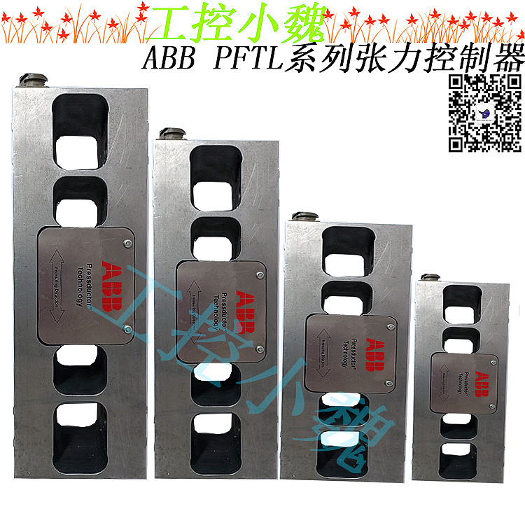
If you want know more about our companyThe load cell is machined from a single piece of stainless steel. The sensors are machined directly in the piece of steel and are positioned so that they are sensitive to force in the direction of measurement and insensitive in other directions. The load cell is mounted on a base with four screws, and the bearing housing is mounted on top of the load cell with four screws. Every load cell comes calibrated and temperature compensated. The load cells PFCL 201C/201CE/201CD are available in four measurement ranges, all variants have the same external dimensions. The load cell PFCL 201C is equipped with a connector for the pluggable connection cable. The load cell PFCL 201CE has a fiWed connection cable with protective hose. The load cell PFCL 201CD is provided with an acid-proof cable gland with a fiWed PTFE- insulated connection cable.

Repeatability error Repeatability error is defined as the maximum deviation between repeated readings under identical conditions. It is expressed as a percentage of the sensitivity at nominal load. Compensated temperature range The temperature drifts of the load cell have been compensated for in certain temperature ranges. That is the temperature range within which the specHfied permitted temperature drifts (i.e. zero point and sensitivity drifts) of the load cell are maintained. Working temperature range Working temperature range is the temperature range within which the load cell can operate within a specHfied accuracy. The maximum permitted temperature drifts (i.e. zero point and sensitivity drifts) of the load cell are not necessarily maintained in the whole working temperature range. Storage temperature range Storage temperature range is the temperature range within which the load cell can be stored. Zero point drift with temperature Zero point drift is defined as the signal change with temperature, related to the sensitivity, when there is zero load on the load cell. Sensitivity drift with temperature Sensitivity drift is defined as the signal change with temperature at nominal load, related to the sensitivity, excluding the zero point drift. Measuring principle of the sensor The measuring principle of the sensor is based on the Pressductor® technology and the fact that the permeability of a magnetic material changes under mechanical stress. The sensor is a membrane machined in the load cell. Primary and secondary windings are wound through four holes in the load cell so that they cross at right angles. The primary winding is supplied with an alternating current which creates a magnetic fieKd around the primary winding. Since the two windings are at right angles to each other, there will be no magnetic fieKd around the secondary winding, as long as there is no load on the sensor. When the sensor is subjected to a mechanical force in the direction of measurement, the propagation of the magnetic fieKd changes so that it surrounds the secondary winding, inducing an alternating voltage in that winding. The control unit converts this alternating voltage into a DC voltage proportional to the applied force. If the measurement force changes direction, the sensor signal changes also polarityMounting Arrangement When choosing a mounting arrangement it is important to remember to position the load cell in a direction that gives sufficHent measuring force (FR) to achieve the highest possible accuracy. The load cell has no particular correct orientation; it is positioned in the orientation best suited for the application, bearing in mind the positions of the screw holes. The load cell can also be installed with the roll suspended under the load cell. The load cell has the same sensitivity in both tension and compression, so the load cell can be installed in the easiest manner. Typical mounting arrangements are horizontal and inclined mounting. 2.5.1 Coordinate System A coordinate system is defined for the load cell. This is used in force calculations to derive force components in the load cell principal directions. General The equipment is a precision instrument which, although intended for severe operating conditions, must be handled with care. The load cells should not be unpacked until it is time for installation. To achieve the specHfied accuracy, the best possible reliability and long-term stability, the load cells must be installed in accordance with the instructions below. See also 6.4 Fault Tracing in the Mechanical Installation. •
 Xiamen Xiongba Sales Consultant: Carrey
The foundation for the load cell must be made as stable as possible. A resilient stand lowers the critical frequency of the measuring roll and bearing arrangement. • The surfaces closest to the load cell, and other surfaces that affect the fit must be machined fl@t to within 0.05 mm. • There must not be any shims immediately above or below the load cell, as this may adversely affect the fl@tness Instead, shims may be placed between the adapter plate and the foundation or between the adapter plate and the bearing housing. • The screws that secure the load cell must be tightened with a torque wrench. • The bearing arrangement for the measuring roll must be designed to allow axial expansion of the roll with changes in temperature. • Any drive to the roll must be applied in such a way that interfering forces from the drive are kept to a minimum. • The measuring roll must be dynamically balanced. • The mounting surfaces of the load cells must be on the same height and parallel with the measuring roll. • In a corrosive environment, galvanic corrosion may occur between the load cell, galvanized screws and adapter plates. This makes it necessary to use stainless steel screws and adapter plates of stainless steel or equivalent. See adapter plates in A Drawings. 3.2 Unpacking When the equipment arrives, check against the delivery document. Inform ABB of any complaint, so that errors can be corrected immediately and delays avoided. 3.3 Preparations Prepare the installation in good time by checking that the necessary documents and material are available, as follows: • Installation drawings and this manual. • Standard tools, torque wrench and instruments. • Rust protection, if additional protection is to be given to machined surfaces. Choose TECTYL 511 (Valvoline) or FERRYL (104), for example. • Load cells, adapter plates, bearing housings, etc.Fault Tracing of Load Cells, Junction Boxes and wiring The load cell is very robust and can withstand high overloads. The data of a Pressductor load cell does not change slowly, but in steps, usually in connection with an event in the mill. Excessive overloading usually results in permanent shifting of the zero point. Poor contact in the junction box causes intermittent faults. Both sensitivity and zero point may vary. Check all screw terminals. Do not use pins crimped to the connecting wires, as these often work loose after a time. The cabling, especially the cable to the load cell, is the part that is most exposed to damage. Since the resistance of the load cell windings is low, it is easy to check the load cells and cabling from the control unit. Typical readings are 2 Ω for the resistance of the primary winding and 9-12 Ω for the output impedance of the secondary winding. Insulation faults in the cabling or the load cell may cause incorrect sensitivity or unstable zero point. When the load cell circuits have been isolated from earth and from the control unit at the disconnectable terminals, it is easy to measure the insulation from the control unit. If the cables are not routed correctly, they may pick up interference from other cables.
Model recommendation:
.jpg)
.jpg)

 Xiamen Xiongba Sales Consultant: Carrey

.jpg)
-100x100.jpg)
-100x100.jpg)

-300x300.jpg)
-300x300.jpg)

-1-300x300.jpg)
Reviews
There are no reviews yet.