
-100x100.jpg)
-100x100.jpg)
Description
Many products have not been listed yet. For more products, please contact us
If the product model is inconsistent with the displayed image, the model shall prevail. Please contact us for specific product images, and we will arrange for photos to be taken and confirmed in the warehouse
We have 16 shared warehouses worldwide, so sometimes it may take several hours to accurately return to you. We apologize for any inconvenience caused. Of course, we will respond to your concerns as soon as possible.
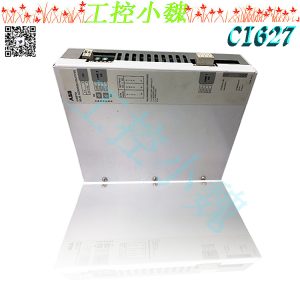
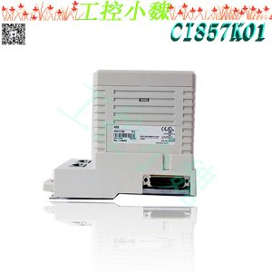
SYN5202a-Z,V221 3BHB006715R0221 Other names:
Synchronous device SYN5202a-Z,V221 3BHB006715R0221
SYN5202a-Z,V221 3BHB006715R0221 synchronization module
Synchronous module SYN5202a-Z,V221 3BHB006715R0221
The SYNCHROTACT 5 digital synchronization device is used for automatic synchronization and parallel connection between generators and the power grid, as well as for parallel connection between already synchronized power grids. The system frequency applicable to this device is 50/60Hz or 16 2/3 Hz. Among them, the SYN 5201 digital synchronous device is a single channel synchronous device, and its components and software design are very reliable, which makes the synchronous device have high safety and can prevent asynchronous closing. The SYN5202 digital synchronous device includes two independent channels composed of different hardware and software. This dual channel characteristic further improves the safety of the synchronous device and can prevent asynchronous closing to the greatest extent. All parameters required for parallelism are stored in one parameter set. This parameter set provides the conditions required for parallelism and the characteristics of voltage and frequency matchers. By providing 7 different parameter sets, the same synchronous device can achieve parallelism under different parallel conditions and voltage and frequency matching characteristics. Different parameter sets can be selected through 7 configurable digital inputs and digital outputs. The data that plays an important role in debugging and controlling the synchronization device can be uploaded or downloaded through PC software SynView or through the keyboard on the synchronization device panel.
Parallel function
The entire automatic parallel process can be divided into the following four basic functional modules:
1. Measurement;
2. Voltage matching and frequency matching;
3. Parallel condition monitoring;
4. Parallel instruction generation.
Variable pulse duration voltage matcher
The voltage matcher issues a regulation command (pulse), whose length is proportional to the current voltage difference, and the scale factor dU/dt can be adjusted according to the voltage regulator. The task of the voltage matcher is to adjust the voltage difference to the middle position of the set tolerance zone, and the length of the adjustment command tpU can be calculated according to the following equation.
Once the voltage difference is adjusted to the target value, the adjustment pulse will stop. The length of the adjustment command should not be lower than a minimum value that can be set. After issuing the adjustment command, the system will wait for a set pulse interval time ts U, so that the actual voltage value can gradually stabilize to the new set voltage value.
Variable pulse duration frequency matcher
The adjustment command (pulse) is issued by the frequency matcher, and the length of the command is proportional to the current slip rate. The scale factor df/dt can be adjusted according to the speed controller. The task of the frequency matcher is to adjust the current slip rate to the midpoint of the difference between the slip rate limit value (the smaller extreme value between the upper and lower limits) and zero. The length of the adjustment instruction tpf can be calculated according to the following equation:
When the slip rate is within the range of 1/3 to 2/3 of the slip rate limit smax, there is no need to adjust it. Once the slip rate reaches zero, the adjustment pulse will immediately stop. The length of the adjustment command should not be lower than a minimum value that can be set. After issuing the adjustment command, the system will wait for a set pulse interval time ts f to gradually stabilize the actual slip rate to the new set value..jpg)
Parallel instruction generation
The generation of parallel instructions for asynchronous power sources is significantly different from the generation of parallel instructions for synchronous power sources or voltage free lines. In this case, both synchronous and asynchronous modes are used simultaneously, and the power source can be both synchronous and asynchronous at any time. In which mode all conditions are met first, the parallel instructions will be used. In the SYN 5202 synchronous device, the relay control in the two channels is independent of each other.
Asynchronous power supply
When generating parallel commands, it is necessary to calculate the required phase advance angle α v through slip s, acceleration ds/dt, line frequency f1, and the set parallel time t on, etc. This allows the system to issue parallel commands in advance, so that when the main contact is connected, the phases of the two parallel power sources are completely consistent
If the measured phase angle difference α and phase advance angle α v are consistent, and all parallel conditions are also met simultaneously (CHK release), a parallel instruction (ORDER) is generated. The length of the generated instruction is always consistent with the set parallel instruction length tp on. If the set instruction length is set to OFF or zero, no parallel instructions will be generated, and the synchronization device only serves as a synchronization checker; Once the monitoring (CHK release) provides the corresponding release, the contact will immediately connect, and when the release stops, the contact will open again.
Synchronous power supply and voltage free lines
If the parallel condition (CHK release) or non live line condition (DB release) is met within the monitoring time t supervisor, then the parallel command is immediately generated as soon as the monitoring time t supervisor ends, which means there is no need to wait until the phase difference exceeds zero.
Multi instruction
Multiple Instruction Function (MUPLIPLE ORD) allows for multiple instructions in a synchronous sequence, or pauses instruction generation after the first parallel instruction in each synchronous sequence is generated.
Test function
In order to cooperate with installation, the SYNCHROTACT 5 synchronous device provides three testing functions:
1. TEST ton (parallel time test): Connect the circuit breaker, determine the parallel time, and adjust the measured voltage;
2. TEST U-Match: Adjust the voltage of the voltage matcher to match the voltage of the voltage regulator;
3. TEST f-Match: Adjust the frequency of the frequency matcher to match the frequency of the governor;.jpg)
Special operation mode
The test mode can be used to check the synchronization function through configurable inputs and outputs (with 7 parameter set options provided)
Check. After completing the corresponding selection and receiving the start signal, the SYNCHROTACT 5 synchronization device enters a locked state, and
Match the voltage and frequency of the generator by adjusting instructions. Parallel instructions are not output through command relays, but rather
Output through a configurable signal relay.
When the instruction generation, voltage matcher, and frequency matcher in the parameter set are all turned off, SYN 5201 and SYN 5202
The synchronous device can be used as a synchronous detector.
By appropriately configuring the input and output, it is possible to alternate the use of automatic and manual modes within the same synchronous device
Control the switch of the same circuit breaker in a dynamic manner.
Software monitoring
In the design of the SYN 5202 synchronous device, different types of processors are used for each channel, and these processors are installed with different software and completely independent measurement devices and instruction relays. This structural design provides a safety guarantee for correct parallel operation, preventing close proximity to parallelism that meets all parallel conditions. If an error occurs, the built-in “watchdog” in the synchronous device will interrupt the operating program and reset it. After resetting, the operating program will automatically start again. This startup program can be executed three times in total. If it still fails, the synchronization device will be completely locked and display the corresponding error message.
Clock synchronization
Two clocks are used in the SYNCHROTACT 5 synchronous device to record the date and time markers in the event recorder and temporary recorder, respectively. There are two ways to synchronize these clocks with external radio clocks:
Relative synchronization through pulses (pulse synchronization): Use the SynView tool to read the time of the connected PC into the device. At the same time, in order to prevent clock time drift during the synchronization process, a periodic pulse was input to the device (at the ClockIN input of connector X1),
Absolute synchronization: Regularly transmit the date and time of the radio clock to the SYNCHROTACT 5 synchronization device through the serial interface (- X2 “clock synchronization”). The type of reference radio clock is Hopf 6870.
All products on this website are special products, and market prices have been fluctuating,
The specific customer service quotation shall prevail, as the product is a new product and the price is not genuine,
Please confirm the model, product, price, and other detailed information with customer service before placing an order. The website has been used,
The new one is for sale, please contact customer service to communicate.
Recommended devices in the same series:
SYN6302-5203
SYN6302-5202
SYN6302-2203
SYN6302-4202
SYN6302-2202
SYN6202-2202
SYN6302-1203
SYN6302-1202
SYN6302-0202
SYN5202-5287
SYN5202-5277
SYN5202-5281
SYN5202-5271
SYN5202-4287
SYN5202-4281
SYN5202-4277
SYN5202-4271
SYN5202-3287
SYN5202-3281
More……
-300x300.jpg)
-300x300.jpg)
Reviews
There are no reviews yet.