

.jpg "DS215TCQAG1BZZ01A(1)")
.jpg "DS215TCQAG1BZZ01A(2)")
-100x100.jpg)
-100x100.jpg)
Description
DS200TCQAG1BHF-W01 DS215TCQAG1BZZ01A- Analog I/O Board is available in stock which ships the same day.
DS200TCQAG1BHF-W01 DS215TCQAG1BZZ01A- Analog I/O Board comes in UNUSED as well as REBUILT condition.
To avail our best deals for DS200TCQAG1BHF-W01 DS215TCQAG1BZZ01A- Analog I/O Board, contact us and we will get back to you within 24 hours.
DS200TCQAG1BHF-W01 DS215TCQAG1BZZ01A Other names:
Controller DS200TCQAG1BHF-W01 DS215TCQAG1BZZ01A
DS200TCQAG1BHF-W01 DS215TCQAG1BZZ01 Aoutput module
Communication module DS200TCQAG1BHF-W01 DS215TCQAG1BZZ01A
Product Description
The GE RST analog I/O board DS200TCQAG1BHF-W01 DS215TCQAG1BZZ01A includes six 34 pin connectors, two 40 pin connectors, and six jumpers. The board also has 6 LEDs. The LEDs are arranged in two rows, with three LEDs in each row. When the board is installed in the driver, it is installed between other boards, and the side of the GE RST analog I/O board DS200TCQAG1 can be seen from the glass front of the board cabinet.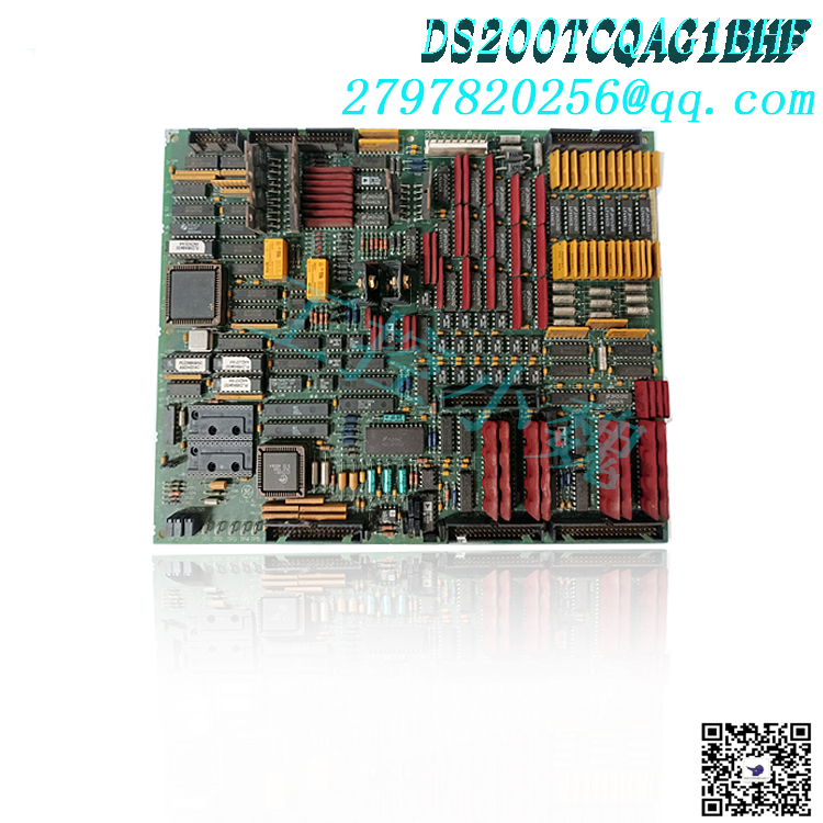
The arrangement of LEDs allows the operator to see them while the drive is running. The operation status of the 6 functions of the LED indicator board and flashing when an activity occurs. To understand the purpose of each LED, you can read the installation instructions provided in the original circuit board at the factory regarding the LED. The driver operator can determine the health status and ongoing processing of the circuit board at a glance.
JA, JB, JD, JE, JG, and 3PL are the IDs assigned to the 34 pin connector. The ID is printed on the surface of the circuit board next to each connector. When you plan to replace a circuit board, check the defective circuit board while it remains in the driver and mark the ID of the connector it is connected to on the ribbon cable. This will accelerate the installation speed of the new board, as you will immediately know where to connect the 34 pin ribbon cable. Hold the connector of the ribbon cable connected to the circuit board and remove it..jpg)
DS200TCQAG1BHF-W01 DS215TCQAG1BZZ01A is an analog I/O board manufactured and designed by General Electric, and is part of the Mark V LM series for turbine control systems The Analog IO Board (TCQA) scales and adjusts the large number of analog signals read into the terminal boards installed on the I/O cores R1, R2, and R3. This set of signals includes LVDT input, servo valve output, thermocouple input, 4-20 mA input and output, vibration input, relay driver output, pulse input, voltage input, and generator and line signals. On the STCA board, some signals are written through the 3PL connector. The TCQC board receives and transmits generator and line signals through the JE connector. The TCQA board scales and adjusts the 420 mA input signal, including fuel flow pressure and compressor stall detection signal.
TCQA connector:.jpg)
2PL – Distribute power to the TCPS board and core.
3PL – Data bus between STCA, TCQA, and TCQE boards in the core, as well as between STCA, TCQA, and TCQE boards in the core. In order to transmit to COREBUS, conditional signals are transmitted on 3PL.
JA – Provides thermocouple input and cold junction correction for the corresponding R1, R2, and R3 magnetic cores connected to JAR/S/T from the TBQA board.
JB – Connect the JBR terminal board on TBQC to transmit 4-20 mA input and output.
JD – Transfer the tripping signal from the R1 core to the TCTG board in the P1 core; Not used in R2 or R3.
TCQA configuration:
Hardware: Use hardware jumpers J1 and J2 to select the milliampere output circuit. The mA output current range (up to 20 mA or up to 200 mA) is configured using J5 and J6. For card testing, connect the RS232 port to J7. J8 activates the oscillator. For detailed information on the hardware jumper settings of this board, please refer to Appendix A and the hardware jumper panel of the operator interface.
Software: The following describes how to input I/O configuration constants for 4-20 mA inputs and outputs, vibration, LVDT position, pulse rate, and thermocouples in the I/O configuration editor of the operator interface.
Pulse rate input circuit:
The TCQA board contains circuits for scaling and adjusting the pulse rate input read from the TCQC board through the JE connector. These signals come from magnetic pickup inputs and TTL (transistor to transistor logic) inputs, and their signals are sent to QTBA and/or PTBA terminal boards. The input of high-pressure shaft speed enters the “R1” core. Additional signals can be used in conjunction with pulse rate input circuits on R2 and R3.
TCQA 4-20 mA input circuit:
The circuits for the 0-1 mA and 4-20 mA input signals are provided by the TCQA board. Read the signal from the TBQC terminal board through the JB connector. The voltage drop is measured by the TCQA board and written to the I/O engine through the 3PL connector, as the sensor current decreases on the load resistor. Use the hardware jumpers on the TBQC wiring board to select the current range of the input signal.
TCQA 4-20 mA output circuit:
The circuit used to drive the 4-20 mA output to the TBQC terminal board through the JB connector is provided by the TCQA board. Typically, these signals are used to power control equipment.
TCQA thermocouple circuit:
TBQA wiring board coupled with thermocouple. The thermocouple cold junction reference used by TCQA to calculate cold junction compensation is provided by a circuit also installed on the TBQA wiring board. The actual temperature read by the thermocouple is determined by the TCQA board using thermocouple input and compensation settings. The I/O engine reads values through the 3PL connector. The I/O configuration constant is used to select the type and curve of the thermocouple.
Xiamen Xiongba Basketball has the largest stock of GE Speedtronic Mark V LM replacement parts. We can also fix your faulty board. WORLD OF Controls can also provide warranty support for unused and rebuilt items. Our expert team provides support for your OEM needs 24/7. Our expert team at WOC is happy to assist you in addressing any automation needs you may have. Please contact our team by phone or email regarding the prices and availability of any parts and repairs.
FAQ on DS200TCQAG1BHF-W01 DS215TCQAG1BZZ01A
What types of inputs are read by DS200TCQAG1BHF-W01 DS215TCQAG1BZZ01A?
DS200TCQAG1BHF-W01 DS215TCQAG1BZZ01Areads LVDT input. The first redundant sensor input of VDC1 and VDC2 also communicates with DS200TCQAG1BHF-W01 DS215TCQAG1BZZ01A in the control processor through a dedicated ribbon cable.
Which voltage regulators are part of the DS200TCQAG1BHF-W01 DS215TCQAG1BZZ01A software?
The digital control regulator is a part of the I/O configuration software on DS200TCQAG1BHF-W01 DS215TCQAG1BZZ01A in each control processor of Mark V.
What happens to DS200TCQAG1BHF-W01 DS215TCQAG1BZZ01A when Mark V malfunctions and commits suicide?
When current fault suicide is enabled on Mark V, the relay on DS200TCQAG1BHF-W01 DS215TCQAG1BZZ01A will be de-energized, and a pair of normally closed contacts on DS200TCQAG1BHF-W01 DS215TCQAG1BZZ01A will short-circuit the output terminals together.
Where can I find the manual for DS200TCQAG1BHF-W01 DS215TCQAG1BZZ01A ?
We can provide you with the manual for DS200TCQAG1BHF-W01 DS215TCQAG1BZZ01A . The manual used with DS200TCQAG1BHF-W01 DS215TCQAG1BZZ01A is the Speedtronic Mark V Turbine Control Application Manual, GEH-6195, which covers the application information of the Mark V Speedtronic controller and provides detailed information about DS200TCQAG1BHF-W01 DS215TCQAG1BZZ01A.
What input formats can DS200TCQAG1BHF-W01 DS215TCQAG1BZZ01A read?
The LVDT input is read by TCQA. A dedicated stripline connects the analog I/O board in the R control processor to the first redundant sensor input of VDC1 and VDC2.
What regulatory agencies are included in TCQA’s software?
The input and output setting software on TCQA in each control processor in Mark V includes a digital control regulator.
How to view the price and availability of DS200TCQAG1BHF-W01 DS215TCQAG1BZZ01A ?
Please contact us at+86 18030177759 for sales or to request a quote.
Model recommendation:
PFCL201C 10KN
DS200FECBG1A GE
GE DS200DDTBG1A
GE DS200DDTBG1A
DS200SHCAG1B
DS215DMCBG1AZZ03B
DS200TCQCG1A
DS200TBQCG1A
DS200TBQCG1ABB
DS2020CMB1206CGDDD8E
DS200DDTBG1A
-300x300.jpg)
Reviews
There are no reviews yet.