Description
Many products are not yet on the shelves, please contact us for more products
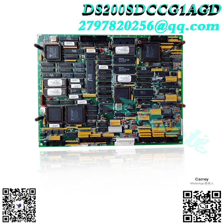
If the product model is inconsistent with the display picture, the model shall prevail. Please contact us for specific product pictures, and we will arrange to take photos in the warehouse for confirmation
We have 76 shared warehouses around the world, so sometimes it may take several hours to return to you accurately, please understand. Of course, we will respond to your concerns as soon as possible.
About DS200TCQCG1BJF
DS200TCQCG1BJF is an RST overflow board, which is part of the GE Speedtronic Mark V gas turbine control system. The DS200TCQCG1BJF RST overflow board is equipped with 24 jumpers and three 40-pin connectors. There are three 34-pin connectors and one 16-pin connector on the board. The ID of the 16-pin connector is JC. JFF, JE, and 6PL are the IDs assigned to the 40-pin connector. Several relays on the GE RST Overflow Board DS200TCQCG1BJF open and close circuits on the board. The relays are connected to the board via leads and require no maintenance.
JFF, 1PL, and JA are the IDs for the 34-pin connector. Ribbon cables use the 40-pin and 34-pin connectors to connect the GE RST Overflow Board DS200TCQCG1BJF to other boards and components in the drive.
This GE DS200TCQCG1BJF board is a bit of a mystery, as it is referred to as a number of different functions in the original GE documentation. This DS200TCQCG1BJF printed circuit board (PCB for short) is considered to be both an RST Overflow Board and an Analog IO Expansion Board. That being said, most official GE instruction manual material for this Mark V Turbine Control System series product refers to it as an Analog IO Expansion Board, so this personalized product page will refer to it as such for the most part.
Hardware Tips and Specifications
Like any Mark V Series product, this DS200TCQCG1BJF Analog IO Expansion Board requires several unique and specific hardware components and component specifications to be incorporated into the internal assembly; the first of which is its three product revisions. Two of these three revisions are intended to improve the general functionality and performance specifications of the DS200TCQCG1 mother printed circuit board, while the third revision is for aesthetics and durability.
The GE RST Overflow Board DS200TCQCG1BJF is populated with 24 jumpers and three 40-pin connectors. It also has three 34-pin connectors and one 16-pin connector. Each hardware element in this Analog IO Expansion Board assembly is provided with a separate reference designator ID. The ID assigned to the 16-pin connector is JC. The IDs assigned to the 40-pin connectors are JFF, JE, and 6PL. The GE RST Overflow Board DS200TCQCG1BJF also contains several relays that are used to open and close circuits on the board. The relays are maintenance-free and are soldered to the board with leads. The IDs for the 34-pin connectors are JFF, 1PL, and JA. The 40-pin connector and the 34-pin connector connect to the ribbon cable that connects the Analog IO Expansion Board DS200TCQCG1BJF to the other boards and components in the drive. It is very important to maintain the cable routing laid out for the cables in the drive when replacing boards. Since the ribbon cable carries signals, improper routing can cause interference from power lines being too close to signal lines. Interference occurs when signal and power lines are routed in parallel, so it is usually best to keep them separate. If they must touch each other, only have them cross each other at a 90-degree angle.
Frequently Asked Questions about the DS200TCQCG1BJF
Are the three major product revisions of this DS200TCQCG1BJF motherboard backwards compatible?
No. Only the first two functional product revisions are considered backward compatible with this DS200TCQCG1BJF analog IO expansion board; because they are both functional revisions.
Which connectors are not typically used when assembling this DS200TCQCG1BJF analog IO expansion board?
Several connectors included in this DS200TCQCG1BJF printed circuit board assembly are not typically used, including connectors labeled 1PL, 6PL, 17PL, VARC, JBU, ARCPL, and CARC.
All products on this website are special products, and market prices have been fluctuating.
Specifically subject to customer service quotation, because the product is a new product, the price is not real,
Please confirm the model and product, price and other details with customer service before placing an order, the website has been used,
New ones are being sold, please contact customer service for communication.
Related product recommendations:
DS200DCFBG1BLC
DS200DCFBG2BNC
DS200DCFBG1BNC
DS200DCFBG2BNC
DS200FECBG1A
DS200DDTBG1A
GE DS200DDTBG1A
DS200SHCAG1B
Board DS200TCQCG1A
DS200TBQCG1A
More……


.jpg)
.jpg)
-300x300.jpg)


admin –
The GE RST overflow board DS200TCQCG1BJF is equipped with 24 jumpers and 3 40 pin connectors. It also has 3 34 pin connectors and 1 16 pin connector. Each individual hardware element in this simulated IO expansion board assembly is equipped with a separate reference indicator ID. The ID assigned to the 16 pin connector is JC. The IDs assigned to the 40 pin connector are JFF, JE, and 6PL.The GE RST overflow board DS200TCQCG1BJF also includes multiple relays for opening and closing circuits on the circuit board. The relay does not require maintenance and is soldered to the circuit board through leads. The IDs of the 34 pin connector are JFF, 1PL, and JA. Connect the 40 pin connector and 34 pin connector to the ribbon cable, and connect the analog IO expansion board DS200TCQCG1BJF to other circuit boards and components in the driver.