
-100x100.jpg)
-100x100.jpg)
Description
Manufacturer General Electric Series Mark V Part Number DS215SLCCG1AZZ01B Product Category LAN Communication Card User Manual GEI-100162B
General Electric F anuc (USA) ▂ DS215SLCCG1AZZ01B ▂
LAN communication board
Working temperature: 40 to 70 ° C Size: 17.8 cm high x 33.02 cm
Availability: In stock
Product Description
DS215SLCCG1AZZ01B is a LAN communication board designed by General Electric for its Mark V board series. Local area network (LAN) communication is performed by isolated and non isolated circuits on the circuit board. Use this LAN card to perform drive communication over the local network. There is a main microprocessor and system memory space on the card. This board can communicate through DLAN and ARCNET local networks.
This board has a LAN control processor or LCP that performs system communication. Use this LCP to handle network communication in and out of DS215SLCCG1AZZ01B. Two EPROM slots are used for onboard storage of LCP software. The communication between the Drive Control Processor (DCP) and LCP occurs in dedicated RAM storage space. There are many connections available on the circuit board to allow for the connection of various system functions. Position 2PL serves as the power connection, while 3PL provides input points for the driver’s control card. 10PL provides LAN I/O terminal board connections for LCP. DLAN and ARCNET communication can be achieved using ARCPL connections. The A module programmer and alphanumeric keyboard provide users with system access to diagnostics and settings.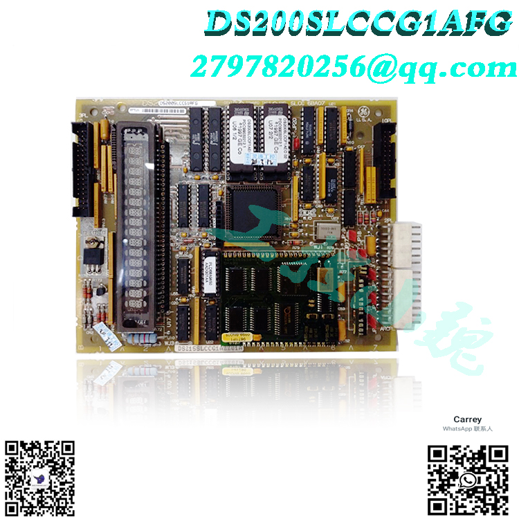
General Electric provides some installation and storage parameters that should be met to protect circuit boards and drivers. The device data sheet and manual contain complete wiring and installation guidelines for DS215SLCCG1AZZ01B. The technical support for this board was initially provided by the manufacturer General Electric.
AX Control’s trusted sales personnel are happy to help you meet all your automation needs. Please contact our team members by phone or email to receive the current prices and availability of all parts and repairs.
FAQ on DS215SLCCG1AZZ01B
Does DS215SLCCG1AZZ01B have a display screen?
Yes, DS215SLCCG1AZZ01B has a 16 digit alphanumeric display and display controller U18, which connects DS215SLCCG1AZZ01B to the programmer module. The programmer module is installed on DS215SLCCG1AZZ01B and plugged into connector KPPL.
What hardware does DS215SLCCG1AZZ01B include?.jpg)
DS215SLCCG1AZZ01B has configurable hardware, including Berg type or manually moved hardware jumpers and jumpers. The berg type jumpers on DS215SLCCG1AZZ01B are identified using the JP naming convention, while the jumpers on DS215SLCCG1AZZ01B are identified using the WJ naming convention.
What networks are DS215SLCCG1AZZ01B connected to?.jpg)
DS215SLCCG1AZZ01B can be connected to DLAN and ARCNET networks through the circuit of DS215SLCCG1AZZ01B. DS215SLCCG1AZZ01B has isolated and non isolated circuits for communication with drivers or actuators.
What is described in the manual of DS215SLCCG1AZZ01B?
DS215SLCCG1AZZ01B manual GEI-100162 is a manual for GE Motors and Industrial Systems LAN communication cards. This manual provides a functional description of DS215SLCCG1AZZ01B, including the connection and installation of DS215SLCCG1AZZ01B. This manual provides application data for DS215SLCCG1AZZ01B, including configurable hardware and software. The manual for DS215SLCCG1AZZ01B provides updates/warranty replacements for DS215SLCCG1AZZ01B.
Function Description
DS215SLCCG1AZZ01B is a LAN communication card developed by GE. It is part of the Mark V control system. It has circuits for communicating with isolated and non isolated drivers or exciters. The programmer module is connected to a 16 digit alphanumeric display (and display controller, U18). The KPPL connector receives the programmer module installed in SLCC. The LAN control processor U1 is the main microprocessor (LCP). Two replaceable EPROMs include LCP software (U6 and U7). U8 and U9 provide LCP dedicated memory. The communication between LCP and the drive control processor (DCP) on the drive control card is carried out through 3PL and dual port RAM (U5). Dual Port RAM [DPR] is the RAM set up as a memory array that can be accessed independently and simultaneously by two microprocessors.
Card connection
Five connectors (labeled as PLs) connect SLCC to other controller boards, external signals, and networks. You can see the SLCC configuration diagram in Figure 1 and the pin signal information of each connector in Tables 2 to 6. These are the connectors connected to other boards:
2PL – ± 5, 15, and 24 V DC I/O between power/interface board (IMCP, DCI, SDCI, or DCFB), driver terminal board (531X305NTBA), or between
Simple Drive Terminal Board (DS200STBA), Drive Control Card, and SLCC
3PL – SLCC input from drive control card
10PL – I/O between LAN I/O terminal board and SLCC
ARCPL – I/O between DLAN and ARCNET signals and cards
KPPL – I/O between programmer module keyboard and card
Circuit board installation
The four brackets on SDCC are the locations for installing SLCC.
The connector KPPL of SLCC accepts the programmer module plug, and SLCC is covered by the module’s keyboard and cover.
Application materials
SLCC includes configurable hardware that must be set up correctly for the application:
Berg type hardware jumper, identified by JP naming convention.
Jumper, identified by WJ naming convention
These jumpers are used for user application options or factory testing. Most jumper options are pre-set at the factory.
Software
The LAN Control Processor (LCP) software included in EPROM U6 and U7 cannot be configured on-site.
EPROM U6 and U7 can be replaced and moved from one board to another. When ordering replacement boards. The EPROM on the old board must be transferred to the new board.
When replacing SLCC (or LCC) and requiring EPROM, specify SLCC to ensure that it includes two EPROMs.
software design
The exciter application program consists of useful software modules that work together as “building blocks” to meet system requirements. Variables are stored in random access memory (RAM), while block definitions and configuration information are stored in read-only memory (ROM) (RAM).
The code is executed by the microcontroller. Traditional simulation control is simulated by the exciter application program. This program utilizes an open architecture system and a pre existing library of building blocks.
Each module has a specific purpose, such as signal level detector, function generator, proportional integral (PI) regulator, AND gate and function generator.
Frequently asked questions
Xiamen Xiongba is willing to assist you in addressing any automation needs. Please contact us by phone or email to inquire about the prices and availability of any parts and repairs.
Frequently asked questions
What is DS215SLCCG1AZZ01B?
It is a LAN communication card developed by GE
What are the main microprocessors on the circuit board?
The main microprocessor on the board is the LAN Control Processor (LCP) located on U1. LCP communicates with the Drive Control Processor (DCP) on the drive control card through 3PL and dual port RAM (U5).
What should be done when ordering replacement boards that require EPROM U6 and U7?
When ordering replacement boards that require EPROM U6 and U7, the EPROM from the old board must be transferred to the new board.
What should be specified when replacing SLCC (or LCC) and requiring EPROM?
When replacing SLCC (or LCC) and requiring EPROM, SLCC should be specified to ensure that both EPROMs are included.
And we promise:
Availability: Orders can now be shipped immediately through DHL, UPS, FedEx, TNT;
Payment method: 100% T/T of inventory goods before shipment;
Warranty: All new or repaired parts have a 12 month warranty period;
Service: 24/7 online service, brand new original packaging.
EPRO JDX004713983473-1-1
-300x300.jpg)
Reviews
There are no reviews yet.