-100x100.jpg)
-100x100.jpg)
Description
DS215TCQAG1BZZ01A – Analog I/O Board is available in stock which ships the same day.
DS215TCQAG1BZZ01A – Analog I/O Board comes in UNUSED as well as REBUILT condition.
To avail our best deals for DS215TCQAG1BZZ01A – Analog I/O Board, contact us and we will get back to you within 24 hours.
DS215TCQAG1BZZ01A Technical Specification
Manufacturer General Electric Series Mark V Part Number DS215TCQAG1BZZ01A Product Category Circuit Board and Firmware User Manual GO-6195 Product Description
The GE RST analog I/O board DS200TCQAG1 includes six 34 pin connectors, two 40 pin connectors, and six jumpers. The board also has 6 LEDs. The LEDs are arranged in two rows, with three LEDs in each row. When the board is installed in the driver, it is installed between other boards, and the side of the GE RST analog I/O board DS200TCQAG1 can be seen from the glass front of the board cabinet.
The arrangement of LEDs allows the operator to see them while the drive is running. The operation status of the 6 functions of the LED indicator board and flashing when an activity occurs. To understand the purpose of each LED, you can read the installation instructions provided in the original circuit board at the factory regarding the LED. The driver operator can determine the health status and ongoing processing of the circuit board at a glance.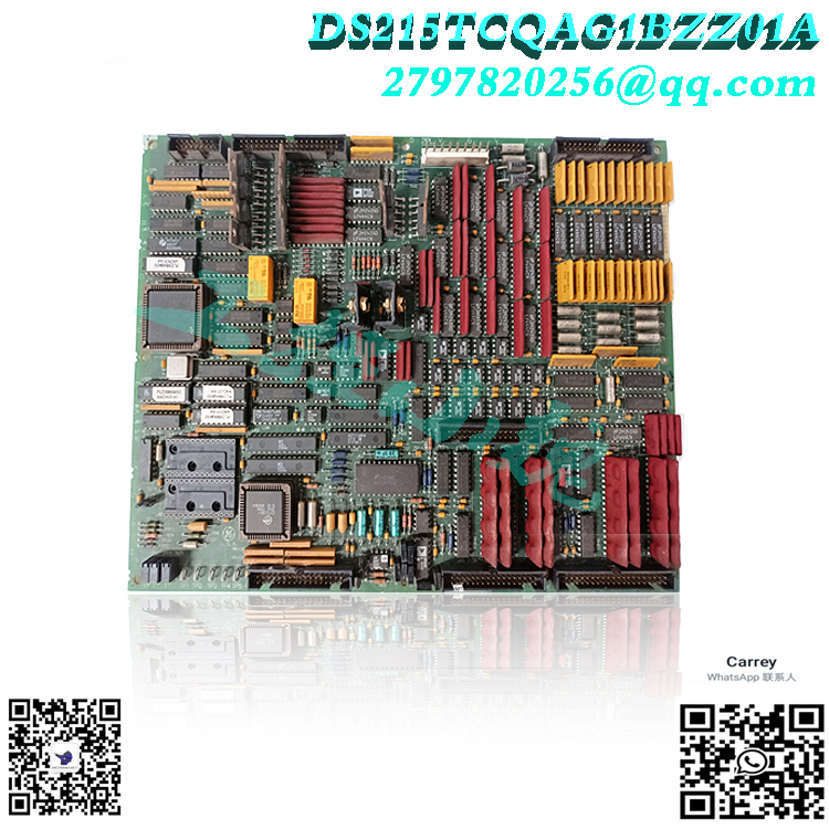
JA, JB, JD, JE, JG, and 3PL are the IDs assigned to the 34 pin connector. The ID is printed on the surface of the circuit board next to each connector. When you plan to replace a circuit board, check the defective circuit board while it remains in the driver and mark the ID of the connector it is connected to on the ribbon cable. This will accelerate the installation speed of the new board, as you will immediately know where to connect the 34 pin ribbon cable. Hold the connector of the ribbon cable connected to the circuit board and remove it.
.jpg)
3PL – Data bus between STCA, TCQA, and TCQE boards in the core, as well as between STCA, TCQA, and TCQE boards in the core. In order to transmit to COREBUS, conditional signals are transmitted on 3PL.
JA – Provides thermocouple input and cold junction correction for the corresponding R1, R2, and R3 magnetic cores connected to JAR/S/T from the TBQA board.
JB – Connect the JBR terminal board on TBQC to transmit 4-20 mA input and output.
.jpg)
JD – Transfer the tripping signal from the R1 core to the TCTG board in the P1 core; Not used in R2 or R3.
TCQA configuration: Hardware: Use hardware jumpers J1 and J2 to select the milliampere output circuit. The mA output current range (up to 20 mA or up to 200 mA) is configured using J5 and J6. For card testing, connect the RS232 port to J7. J8 activates the oscillator. For detailed information on the hardware jumper settings of this board, please refer to Appendix A and the hardware jumper panel of the operator interface. Software: The following describes how to input I/O configuration constants for 4-20 mA inputs and outputs, vibration, LVDT position, pulse rate, and thermocouples in the I/O configuration editor of the operator interface. Pulse rate input circuit: The TCQA board contains circuits for scaling and adjusting the pulse rate input read from the TCQC board through the JE connector. These signals come from magnetic pickup inputs and TTL (transistor to transistor logic) inputs, and their signals are sent to QTBA and/or PTBA terminal boards. The input of high-pressure shaft speed enters the “R1” core. Additional signals can be used in conjunction with pulse rate input circuits on R2 and R3.
TCQA 4-20 mA input circuit:
The circuits for the 0-1 mA and 4-20 mA input signals are provided by the TCQA board. Read the signal from the TBQC terminal board through the JB connector. The voltage drop is measured by the TCQA board and written to the I/O engine through the 3PL connector, as the sensor current decreases on the load resistor. Use the hardware jumpers on the TBQC wiring board to select the current range of the input signal.
TCQA 4-20 mA output circuit:
The circuit used to drive the 4-20 mA output to the TBQC terminal board through the JB connector is provided by the TCQA board. Typically, these signals are used to power control equipment.
TCQA thermocouple circuit:
TBQA wiring board coupled with thermocouple. The thermocouple cold junction reference used by TCQA to calculate cold junction compensation is provided by a circuit also installed on the TBQA wiring board. The actual temperature read by the thermocouple is determined by the TCQA board using thermocouple input and compensation settings. The I/O engine reads values through the 3PL connector. The I/O configuration constant is used to select the type and curve of the thermocouple.
Frequently asked questions
What input formats can DS215TCQAG1BZZ01A read?
The LVDT input is read by TCQA. A dedicated stripline connects the analog I/O board in the R control processor to the first redundant sensor input of VDC1 and VDC2.
What regulatory agencies are included in TCQA’s software?
The input and output setting software on TCQA in each control processor in Mark V includes a digital control regulator.
What types of inputs are read by DS215TCQAG1BZZ01A?
DS215TCQAG1BZZ01A reads LVDT input. The first redundant sensor input of VDC1 and VDC2 also communicates with DS215TCQAG1BZZ01A in the control processor through a dedicated ribbon cable.
Which voltage regulators are part of the DS215TCQAG1BZZ01A software?
The digital control regulator is a part of the I/O configuration software on DS215TCQAG1BZZ01A in each control processor of Mark V.
What happens to DS215TCQAG1BZZ01A when Mark V malfunctions and commits suicide?
When current fault suicide is enabled on Mark V, the relay on DS215TCQAG1BZZ01A will be de-energized, and a pair of normally closed contacts on DS215TCQAG1BZZ01A will short-circuit the output terminals together.
All products on this website are special products, and market prices have been fluctuating,
The specific customer service quotation shall prevail, as the product is a new one and the traps are not real,
Please confirm the model, product, price, and other detailed information with customer service before placing an order. The website has been used,
New for sale, please contact the website https://www.weikunfadacai1.com/ Customer service communication.
Popular model recommendations:
DS215TCQAG1BZZ01A
DS200TCQAG1BHF-W01
DS215KLDCG1AZZ03A
DS215SDCCG3AZZ01B
DS215KLDBG1AZZ03A
DS215DMCBG1AZZ03B
DS215SLCCG2AZZ01B
DS215KLDAG1AZZ02A
DS215KLDBG1AZZ03B
DS215GHDQG5AZZ01
-300x300.jpg)
admin –
Manufacturer General Electric Series Mark V Part Number DS215TCQAG1BZZ01A Product Category Circuit Board and Firmware User Manual GO-6195 Product Description
The GE RST analog I/O board DS200TCQAG1 includes six 34 pin connectors, two 40 pin connectors, and six jumpers. The board also has 6 LEDs. The LEDs are arranged in two rows, with three LEDs in each row. When the board is installed in the driver, it is installed between other boards, and the side of the GE RST analog I/O board DS200TCQAG1 can be seen from the glass front of the board cabinet.