Description
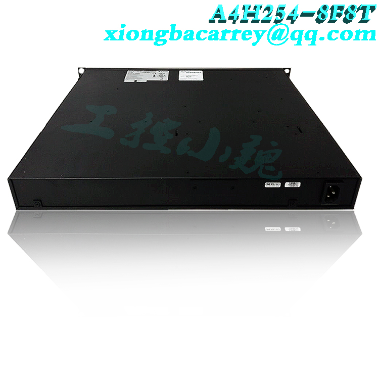
The Extreme Networks S series stream based switch series brings high-performance distributed switching to network access layers, distribution layers, enterprise/campus cores, and data centers. The S series includes 8-slot S8, 6-slot S6, 4-slot S4, 3-slot S3, 1-slot S1A chassis, and a fixed configuration S series independent cabinet (SSA). The S series provides the highest switching port density per rack unit available in the market, and is forward-looking and scalable, providing an overall system capacity of up to 9.5 Tb. All chassis support PoE and PoE+based on 802.3af and 802.3at (high power) standards through integrated or field installable power systems. Multiple I/O modules have been designed and optimized to be deployed in the network access layer, distribution layer, and S-series, providing a highly elastic distributed switching and routing architecture. Each module is embedded with management and control functions,

.jpg)
.jpg)
1. Approximately 152 cm (5 feet) away from the power supply, 3 44.5 cm (19.4 inches) for proper ventilation, 24.45 cm (1.75 inches) for each switch. (Vertical clearance of 4 41.9 cm (16.5 inches) for proper ventilation depends on the number of stacked switches.) To install the switch in a 19 inch rack, you need to: ● Two rack mounting brackets and mounting screws (rack mounting kit) included with the switch. Four customer provided screws for connecting the switch to a standard 19 inch rack. Enterasys A4 Fast Ethernet Switch Hardware Installation Guide 2-3 Connection Stack Cable switch stacks can be connected in a closed loop or daisy chain. In a closed loop, all switches are sequentially connected, and the last switch in the stack is connected back to the first switch. In a daisy chain configuration, the cable that connects back to the first switch is not installed in the closed loop. The advantage of closed loop is redundancy, which eliminates any single point of failure. Up to eight switches can be stacked together and connected through standard UTP Class 5 or better cables. Stacking cables allows for stacking to operate with a single IP address. Figure 2-4 shows an example of a four height chimney connected in a closed-loop configuration. All STACK DOWN and STACK UP connectors are used for installation. Stacked cable connections are from the STACK DOWN connector of one switch to the next switch in the STACK UP connection stack. The stack cable of the STACK DOWN connector connects the switch at the top of the stack to the close loop of the stack UP connector at the bottom of the stack in a daisy chain configuration, without making a cable connection. Regarding the operation of A4 switches in stacking, A4 switches are stackable switches that can be adjusted and expanded to help meet your network needs. These switches are stacked groups of up to eight A4 switches. Note: The A4H model switch can only be stacked with other A4H model switches. A4H switches with non A4H switches cannot be stacked. That is to say, A4 switches are not stacked with A2 switches. Once installed in the stack, the behavior and performance of the switch are like a single switch. Therefore, you can start with one switch and add more switches as the network expands. You can also mix different products from the A4H series in a single stack to provide the required port combination types and functions to meet the requirements of various applications. In all cases, the switch is executed as a large product and managed as a single network entity. When installing and connecting switches according to the instructions in “Connecting Stacked Cables” on pages 2-5, the following situations occur during initialization: ● The switch that manages the stack is automatically established and referred to as a manager switch. All other switches are established as member switches in the stack. The hierarchical structure of the switch responsible for the backup manager function is also determined to be removed from the stack in the event of a current manager failure, power outage, or disconnection. The Console port on the manager switch remains active for out of band (local) switch management, but the Console port on each member switch is disabled. This allows you to set the IP address and system password using a single console port. Each switch can now be configured locally using only the console port of the manager, or in band using remote devices and the CLI command set described in this section. For various types of programs, refer to “Connecting to Local Console Port Management” for connections to console ports, see pages 2-18. After creating a stack (once multiple switches are interconnected), the following situation occurs: 1. The switch (unit) ID is arbitrarily assigned on a first come, first served basis. 2. Save the switch ID for each module. Then, every time the switch is powered on, it initializes with the same switch ID. This is for port specific information (for example: fe.4.12 is the 12th Fast Ethernet port on switch 4). 3. The management election process uses the following priorities to assign manager switches: a previously assigned/selected manager switch b. Management specified priority (values 1-15) C. Hardware preference level d. Maximum MAC address
Popular model recommendations:


-100x100.jpg)
-100x100.jpg)
-300x300.jpg)
Reviews
There are no reviews yet.