-100x100.jpg)

Description
Many products are not available yet, please contact us for more products
If the product model is inconsistent with the display picture, the model shall prevail. Please contact us for specific product pictures, and we will arrange to take photos in the warehouse for confirmation
We have 76 shared warehouses around the world, so sometimes it may take several hours to return to you accurately, please understand. Of course, we will respond to your concerns as soon as possible.
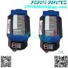
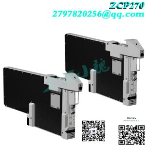
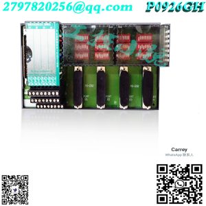
FCP270 Other names:
Editable controller FCP270
FCP270 analog module
Input and output module FCP270
Foxboro Invensys’s FCP270 field control processor is a high-reliability, fault-tolerant control processor designed for industrial automation and process control systems. It is part of the Foxboro I/A Series distributed control system (DCS) developed by Invensys (now part of Schneider Electric). Known for its high reliability and redundancy features, the FCP270 is suitable for critical application scenarios that require continuous operation.
Main features of FCP270
Purpose: As the core control unit of the distributed control system (DCS), it realizes process control, logic operation and data acquisition.
Fault-tolerant design: FCP270 adopts redundant hardware design, including processor, power supply and communication interface, to ensure that the system can continue to operate in the event of hardware failure, support automatic failover, and minimize downtime.
High performance: It can handle complex control strategies and a large number of I/O points, suitable for high-demand industrial applications, and supports fast control logic execution and real-time processing.
Integration with Foxboro I/A Series: It is fully compatible with Foxboro I/A Series DCS and can be seamlessly integrated with other system components (such as I/O modules, workstations and communication networks). It supports multiple communication protocols, including Foxboro’s proprietary protocols and industry standard protocols.
Redundancy options: It supports redundant configuration of processors, power supplies and communication paths to ensure high availability and reliability. Redundancy can be configured at the hardware and software levels.
Scalability: The system is highly scalable, and users can add more FCP270 processors or I/O modules as needed..jpg)
Diagnostics and maintenance: Built-in advanced diagnostic functions can quickly identify and troubleshoot faults, support hot-swappable components, and replace faulty parts without downtime, simplifying the maintenance process.
Environmental adaptability: Designed for harsh industrial environments, it can withstand extreme temperatures, vibrations, and electrical noise.
Application areas
FCP270 is widely used in the following industries:
Oil and gas
Power generation
Chemical processing
Pharmaceutical manufacturing
Water and wastewater treatment
Critical process control: such as continuous production processes (refining, polymerization reactions).
Safety instrument system (SIS): Executes safety interlock logic as a redundant controller.
Asset optimization: Integrates advanced control strategies (such as model predictive control MPC).
Fault-tolerant and redundant design
The fault-tolerant design of FCP270 ensures that the system can continue to operate when a component fails, which is achieved in the following ways:
Dual processors: If one processor fails, the other processor automatically takes over to ensure that the control process is not interrupted.
Redundant power supply: Even if one power supply fails, the system can continue to supply power.
Redundant communication paths: Ensure that communication between the processor and other system components is not interrupted.
Technical features
Hardware architecture:
Processor: High-performance CPU (specific model requires reference to official documents), supporting complex control algorithms.
Memory: Large-capacity flash memory (for program storage) and RAM (for dynamic data).
I/O interface: Supports multiple signal types (4-20mA, digital quantity, pulse, etc.), and can expand remote I/O.
Software functions:
Control language: Based on IEC 61131-3 standard (such as FBD function block diagram, ST structured text).
Integrated tool: Foxboro Control Studio (for configuration, debugging and diagnosis).
Communication protocol: Supports mainstream protocols such as Modbus, HART, and Foundation Fieldbus.
User focus
Redundant configuration: Confirm whether the system needs to be configured with dual power supplies and dual networks to enhance overall fault tolerance, and check the redundancy options of I/O modules (such as dual-channel input).
Maintenance and upgrade: Support online program download to reduce downtime. Firmware upgrades must follow the official process of Schneider Electric.
Troubleshooting: Use built-in diagnostic tools (such as LED status indication and log records) to quickly locate problems, and regularly test the redundant switching function to ensure reliability.
Expansion suggestions
System expansion: The control scale can be expanded by adding I/O expansion racks or integrating third-party devices (such as PLCs and RTUs).
Network security: Consider adding a firewall or security module in accordance with the IEC 62443 standard.
Summary
Foxboro Invensys’s FCP270 field control processor is a high-reliability, high-availability industrial control solution, especially suitable for critical process control systems that require fault tolerance and redundancy. Its integration with Foxboro I/A Series DCS, redundant design, and powerful diagnostic capabilities make it an ideal choice for industrial automation.
All products on this website are special products, and market prices are always fluctuating.
Specific quotations are subject to customer service, because the products are new, the prices are not real.
Please confirm the model and product, price and other details with customer service before placing an order. The website has been used.
New ones are on sale, please contact customer service for communication.
Model recommendation:
FCP280 FOXBORO
FCP270 P0917YZ FOXBORO
FCP280 RH924YA FOXBORO
FOXBORO H92904CC0500
FOXBORO H929049B0500
FBI10E FOXBORO
FBM02 FOXBORO
FBM03 FOXBORO
FBM04 FOXBORO
FBM05 FOXBORO
FBM07 FOXBORO
FBM09 FOXBORO
FBM10 FOXBORO
FBM12 FOXBORO
FBM18 FOXBORO
FBM201 P0914SQ
FBM201D P0922YK
FBM201E P0924TR
FBM202 P0926EQ
FBM203 P0914SV
FBM204 P0914SY
FBM206 P0916CQ
FBM207 P0914TD
FBM207B FOXBORO
FBM207C RH917GY
FBM208 P0914TB
FBM211 FOXBORO
FBM214 FOXBORO
FBM214B P0927AH
FBM215 FOXBORO
FBM216 P0922VV
FBM216B P0927AJ
FBM218 P0922VW
FBM219 RH916RH
FBM223 P0917HD
More……

admin –
Foxboro Invensys’s FCP270 field control processor is a high-reliability, high-availability industrial control solution, especially suitable for critical process control systems that require fault tolerance and redundancy. Its integration with Foxboro I/A Series DCS, redundant design, and powerful diagnostic capabilities make it an ideal choice for industrial automation.