Description
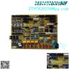
DS200DDTBG1A-LCI auxiliary I/O terminal board is in stock and will be shipped on the same day.
The DS200DDTBG1A-LCI auxiliary I/O terminal board is in an unused and rebuilt state.
If you need to get the best discount on DS200DDTBG1A – LCI auxiliary I/O terminal board, please contact us and we will reply to you within 24 hours.
DS200DDTBG1A Other names:
Controller module DS200DDTBG1A
DS200DDTBG1A main control board
Analog module DS200DDTBG1A
Function description:
DS200DDTBG1A is an LCI auxiliary I/O terminal board manufactured and designed by General Electric, belonging to the Mark V series used in GE Speedtronic control systems. DS200DDTB board (DDTB) is a high-voltage terminal board used for auxiliary I/O signal system connections. This board is connected to the DS200ADMA (ADMA) analog to digital module sub board installed on the DS200DSPC (DSPC) digital signal processor control board. High density connectors and ribbon cables connect the DDTB to the ADMA board. The power supply for DDTB is provided by the ADMA board. DDTB provides signal conditioning, scaling, buffering, and isolation to make harsh environment system level signals accessible to the digital signal processor (DSP) of the DSPC board. External wiring connections for high-voltage signals, contact I/O, current measurement (via low-level Hall effect devices), or high current CT can be connected to the DDTB terminal. The DDTB board has G1 and G2 versions. G2 lacks some functions of G1 and has provided explanations where applicable.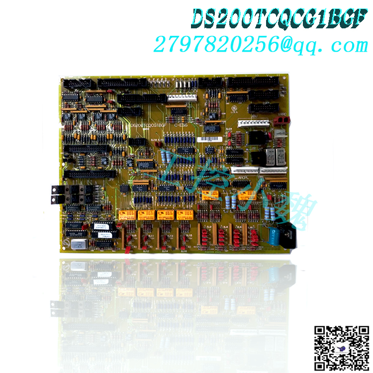
Features:
High voltage AC input: There are two isolated inputs used to connect high-voltage AC signals. They use step-down transformers, passive filters, and buffers to provide ± 5 V peak to peak signals (applying 693 V root mean square value) to the VCO input of the ADMA board. These inputs have separate screw terminals with a rated and isolated voltage of 1000 V peak transient.
High current signal input: There are six charged current response resistors for input, suitable for ± 5 ampere continuous current signals (for CT input). These inputs use differential buffering and can withstand ± 12V common mode voltage. Each input is filtered and scaled. These inputs have screw type terminal blocks and are protected against voltage surges.
Low current signal input: There are three charged current response resistors for input, suitable for ± 0.224 ampere continuous current signals (used for LEM current sensor signals). These inputs use differential buffering and can withstand a common mode voltage of ± 12 V. Each input is filtered and scaled. These inputs have screw type terminal blocks and are protected against voltage surges.
4-20 mA current loop input: There is a requirement to reassign two of the CT or LEM input channels to a 4-20 mA current loop input signal receiver. This alternative allocation is done by resetting certain jumpers. The input resistance is 192 ohms, and the analog input is offset, so 0 mA produces negative full-scale and 20 mA produces positive full-scale. Open loop detection and input standardization are managed by software.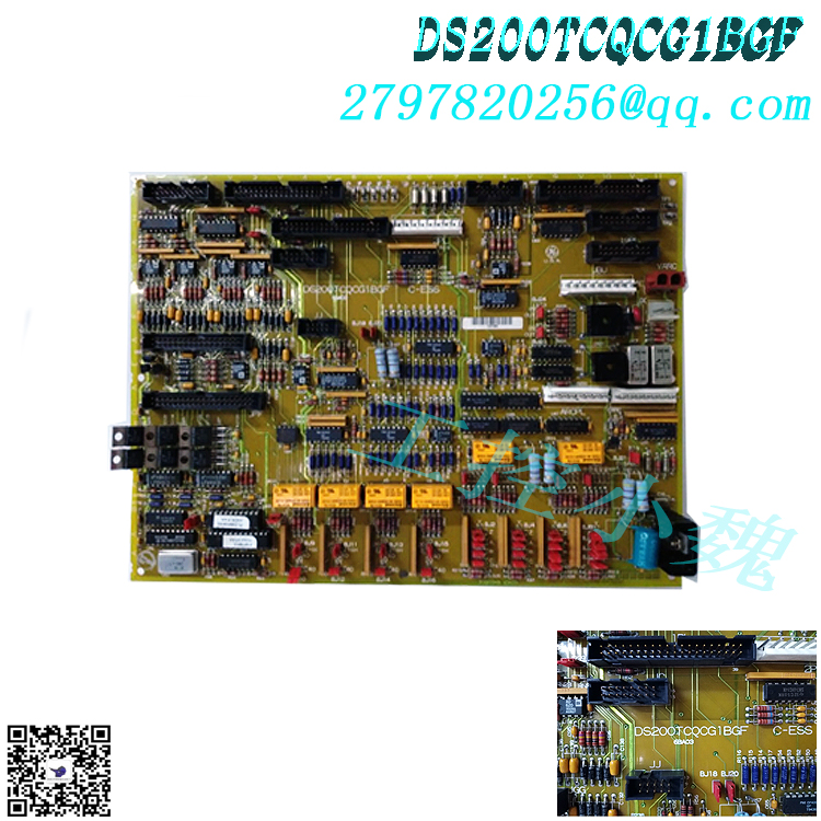
Non dedicated voltage input: Provides a differential input voltage amplifier for powering the analog VCO input on the ADMA board. The gain of this amplifier is 1/2, allowing for a ± 10 V input signal range. These inputs have screw type terminal blocks and are protected against voltage surges.
4-20 mA current output: Two analog outputs also drive the current source output buffer to support the 4-20 mA current loop output signal. The voltage and current outputs are always active and can be used separately or together by connecting to their respective output terminals. There is an inversion and gain stage in the 4-20 mA driver, so a+5 V input from the ADMA board will result in an output of 4 mA, while a -5 V input will result in an output of 20 mA. Output of 0 mA is not allowed to avoid confusion with open-loop detection.
The DS200DDTBG1A model is known as an auxiliary input/output terminal board, and information about it can be found on page 20 of the GEH-6373 series manual. This model is most suitable for use as a terminal board for all auxiliary inputs and outputs. There is a parts manual labeled GEH-100219, which provides detailed information on functions, general characteristics, application data, as well as warranty and replacement information.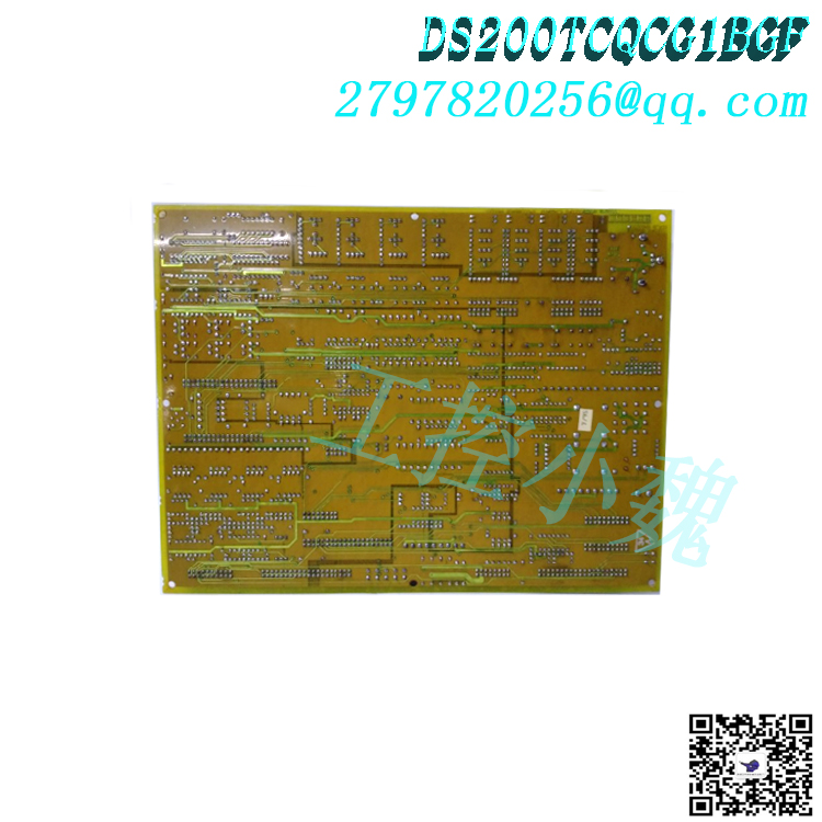
In the DS200DDTBG1A model, there is an electronic ID memory function that can only be added, which includes all circuit board identification and hardware revision information. To access this memory, you must use a single wire LAN so that the connected DSPC circuit board can recognize the circuit boards present in the system.
The DS200DDTBG1A model is equipped with a 4-20 mA current loop input, allowing for reassignment of LEM or CT input channels within the model. To perform this function, certain jumpers must be reset. This model is also equipped with 33 testing points, which can be used for signal measurement. This model has a total of 17 LEDs, with one LED on the board indicating the status of the DS200DDTBG1A board, while the other fifteen LEDs are driven by software and hardware.
Common problems:
What is LCI auxiliary I/O terminal board?
LCI auxiliary input/output terminal board is a device used for auxiliary input/output operations in various electronic systems. It serves as the interface between the main controller and external devices.
What are the main functions of LCI auxiliary I/O terminal board?
The main functions include providing additional input/output channels, facilitating communication between different components of the system, and enabling control or monitoring of external devices.
What types of devices can be connected to LCI auxiliary I/O terminal boards?
According to the specific requirements of the system, various devices such as sensors, actuators, switches, relays, and other peripheral devices can be connected to the terminal board.
What is DS200DDTBG1A terminal board?
DS200DDTBG1A is an LCI auxiliary I/O terminal board used for the GE LS2100 control system.
Which manual is most suitable for assisting with the operation and installation of the DS200DDTBG1A board?
There is a parts specific manual labeled GEI-100219 LCI auxiliary I/O terminal board that can help meet operational and installation needs, as well as a series of manuals labeled GEH-6373 load commutation inverter user manual. Both manuals can be found in the manual tab above.
Where does the power supply for DS200DDTBG1A board come from?
The power supply for the DS200DDTBG1A board is provided by the accompanying ADMA board.
The DS200DDTBG1A board has high-voltage AC input, high current signal input, low current signal input, and 4-20 mA current loop input, but also has non dedicated voltage input. What is a non dedicated voltage input?
Non dedicated voltage input is provided through a differential input voltage amplifier, which feeds the analog VCO input to the ADMA board. These inputs consist of screw type terminal blocks and are protected against voltage surges.
What are the 12 jumpers on the DS200DDTBG1A board used for?
The purpose of the jumper is to redistribute the LEM and CT input channels to become inputs for 4-20 mA current loop signals.
What are the four voltage outputs on the DS200DDTBG1A board and what is their composition?
The four voltage outputs on the DDTB board are buffered analog outputs that can be obtained through screw terminals. Each output has a 200 ohm series resistor that isolates the amplifier from the customer connection. The buffer output includes an amplifier with a gain of 2, which can provide an output range of ± 10 V, while the output range of the connected ADMA board is ± 5 V.
All products on this website are special products, and market prices have been fluctuating,
Please refer to the customer service quotation for details, as the product is new and the price is not genuine,
Please confirm the model, product, price, and other detailed information with customer service before placing an order. The website has been used,
The new one is for sale, please contact customer service for further communication.
Model recommendation:
DS200TCQCG1BBA
DS200TCQBG1B
DS200TBQCG1AAA
DS200TCQBG1BCA
DS200TCCBG3BED
DS200TCQAG1BHF-W01
DS200TCQAG1BHF-W01
DS200TCDAH1BHE
DS200TCQBG1BCB
DS200TCPSG1AEE
more……


-300x300.jpg)
Reviews
There are no reviews yet.