-100x100.jpg)
-100x100.jpg)
Description
Many products have not yet been launched, please contact us for more products
If the product model does not match the displayed image, the model shall prevail. Please contact us for specific product images, and we will arrange for photos to be taken in the warehouse for confirmation
We have 16 shared warehouses worldwide, so sometimes it may take several hours to accurately return to you. We apologize for any inconvenience caused. Of course, we will respond to your concerns as soon as possible.
DS200KLDAG1ACC Other names:
Controller module DS200KLDAG1ACC
DS200KLDAG1ACC Input/Output Module
Main control board DS200KLDAG1ACC
Regarding DS200KLDAG1ACC
The General Electric Mark V DS200KLDAG1ACC keyboard LED display board is an important component of the Mark V turbine control system series, providing advanced visual data representation for effective turbine management. Its integration with the modular Mark V system and its advanced features highlight its importance in ensuring optimal turbine control and operation. As indicated by its complete extended series name, the Mark V series of DS200KLDAG1ACC printed circuit boards, or PCBs for short, has specific applications in popular and compatible control and management systems for wind, steam, and gas turbine automatic drive components. The Mark V series of this DS200KLDAG1ACC PCB can also be defined as one of General Electric’s final product lines, utilizing its patented Speedtronic control system technology, which was first introduced in the mid to late 1960s along with the Mark I series. The Mark V series of the DS200KLDAG1ACC product line, although updated in control system technology, is generally considered to have insufficient updates as production was halted due to obsolescence in the years following its initial release. This DS200KLDAG1ACC PCB is not the original design product for its specific Mark V series functional role; That is to say, the DS200KLDAG1 mother printed circuit board is missing three important product revisions of this DS200KLDAG1ACC PCB.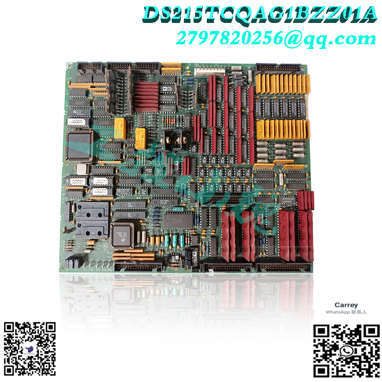
Hardware tips and specifications
The Normal Make V series component of this DS200KLDAG1ACC PCB consists of a large rectangular substrate and seven auxiliary boards labeled DS200DSPA. This DS200KLDAG1ACC printed circuit board product is considered to have a normal Mark V series assembly type, which is somewhat surprising as similar Mark V series daughter board products seem to have DS215 or DS2020 special series labels in their respective functional GE product numbers. The auxiliary board of this DS200KLDAG1ACC PCB is interconnected with the main board through brass pin connectors, forming a robust integrated display system. The main DS200KLDAG1ACC board includes necessary components such as jumper switches, connectors, resistors, resistor network arrays, diodes, transistors, capacitors, and integrated circuits. It is worth noting that DS200KLDAG1ACC adopts advanced technologies, including field programmable gate arrays, oscillation chips, and EEPROM. The voltage protection in the DS200KLDAG1ACC button/LED/display board assembly is handled through a series of standardized voltage limiting hardware components, including various types of capacitors, resistors, and diodes. Since this DS200KLDAG1ACC product belongs to the outdated traditional GE product family, it is not surprising to find that it is not recorded in detail in any of the original Mark V series instruction manual materials available on the Internet. In view of this, the DS200KLDAG1ACC functional product number itself can be regarded as a powerful source of hardware components and component specification information for the DS200KLDAG1ACC board, encoding various detailed information of the DS200KLDAG1ACC board in a series of functional naming blocks. For example, the DS200KLDAG1ACC functional product number starts with the DS200 series label, indicating the normal Mark V series assembly and domestic location of the original manufacturing of this DS200KLDAG1ACC product. Other related hardware details revealed through the DS200KLDAG1ACC feature product number include this Mark V series PCB:.jpg)
KLDA functional product abbreviation
Group 1 Mark V Series Product Grouping
Common PCB protective coating style
Revision of A-level primary functions
C-level secondary function revision
Revision of C-level artwork configuration
The main purpose of the DS200KLDAG1ACC board is to provide a comprehensive visual representation of key digital data related to turbine management. It is equipped with a ten digit LED display on each DS200DSPA auxiliary board, which enables precise and intuitive data presentation. The LED indicator lights are divided into eight rows, each row containing four LEDs. The keyboard LED display panel helps to monitor and analyze important turbine parameters in real-time, enabling operators to make informed decisions and take appropriate measures in a timely manner. The Mark V system is known for its modular architecture, which allows for the replacement of individual circuit boards as needed. The DS200KLDAG1ACC board is an essential part of this modular ecosystem and can seamlessly communicate with other circuit boards through ARCNET connectivity. Its interconnectivity and compatibility make it an important component in ensuring the overall efficiency and functionality of the Mark V turbine control system..jpg)
Frequently Asked Questions about DS200KLDAG1ACC
What are the functions of DS200KLDAG1ACC?
This panel is equipped with a ten digit LED display screen and an interlocking auxiliary board, which can monitor and analyze important parameters in real time. This feature enables users to make informed decisions and take swift action to ensure optimal control and operation of the turbine system.
Are the three major revisions to the DS200KLDAG1ACC PCB considered backward compatible?
It’s not possible. Only the first two significant revisions of this DS200KLDAG1ACC PCB can be considered backward compatible as they exist as functional styles for product revisions.
All products on this website are special products, and market prices have been fluctuating,
Please refer to the customer service quotation for details, as the product is new and the price is not genuine,
Please confirm the model, product, price, and other detailed information with customer service before placing an order. The website has been used,
The new one is for sale, please contact customer service for further communication.
Model recommendation:
DS200SDCCG1ACA
DS200TCDAH1BHE
DS200PCCAG10ACB
DS215TCQAG1BZZ01A
DS200TCQAG1BHF-W01
DS200KLDAG1ACC
DS200SDCIG1AFB
DS200DSFBG1A
DS200SHVMG1AED
DS200UCPBG6AFB
DS200TCQCG1BJF
DS200DCFBG1BLC
DS200DCFBG2BNC
DS200DCFBG1BNC
DS200DCFBG2BNC
DS200FECBG1A
DS200DDTBG1A
DS200DDTBG1
DS200SHCAG1B
IS200WEORG1A
IS200ESELH1A
IS200AEPGG1AAA
IS200TSVCH2AED
IS200EPMCH1
IS200JPDGH1A
IS200ECTBG1ADE
IS200WETAH1AGC
IS200EXHSG3REC
IS200JPDSG1A
more……
-300x300.jpg)
Reviews
There are no reviews yet.