-100x100.jpg)
-100x100.jpg)
Description
DS200TCQCG1A – Analog IO Expander Board is available in stock which ships the same day.
DS200TCQCG1A – Analog IO Expander Board comes in UNUSED as well as REBUILT condition.
To avail our best deals for DS200TCQCG1A – Analog IO Expander Board, contact us and we will get back to you within 24 hours.
Product Description
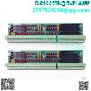
The GE RST Overflow Board DS200TCQCG1A is populated with 24 jumpers and 3 40-pin connectors. It also has 3 34-pin connectors and 1 16-pin connector. The ID assigned to the 16-pin connector is JC. The IDs assigned to the 40-pin connectors are JFF, JE, and 6PL. The jumpers on the GE RST Overflow Board DS200TCQCG1A serve to enable the installer to configure the board for the exact needs of the facility. When the original board is installed, the installer will review the information in the installation guide provided with the board. It contains a description of the jumpers and how the position of the jumpers can change how the board processes. By conferring with the engineering staff at the facility, the installer can set the jumpers to better meet the requirements of the facility. This is part of the drive installation procedure and might require some preinstallation communications between the installer and representatives from the facility to decide how best to set the jumpers.
However, once done, the jumpers stay in place and further configuration is not necessary. This is especially helpful when you plan to replace the board due to the fact that the installed board is defective. The only configuration necessary is to set the jumpers on the replacement board to match the jumper positions on the old board. To do that place the old board on a flat and clean surface. Then, wear a wrist strap and remove the replacement board from the sealed static protective bag. Place the board next to the old board and compare the jumper positions.
FUNCTIONAL DESCRIPTION:
DS200TCQCG1A is an Analog IO Expander Board manufactured and designed by General Electric as part of the Mark V LM Series used in gas turbine control systems. For additional analog signals read from the I/O cores’ terminal boards, the Analog IO ExpanLVDT and LVDR excitation is provided by the TCQC board. The core’s TCQC board contains the IONET termination for and. The TCQC has that IONET termination if the optional 21> is installed. The TCQC board scales and conditions the mA input for the megawatt transducer signal before writing it to the STCA board using the 19PL connector. The TCQC board scales and conditions the pulse rate inputs. The liquid fuel flow signals and high-pressure shaft speed signals are typically scaled on the TCQC board and written to the TCQA board via the JE connector in the “R1” core. Through the JE connector, the STCA board and TCQC board exchange generator and line signals.
TCQC CONFIGURATION:
HARDWARE: The output current range for the servo outputs is set using the TCQC board’s first 16 hardware jumpers. The source output resistance is chosen by the odd-numbered jumpers, whereas the even-numbered jumpers choose the feedback scaling. For servos 1 through 4, additional feedback scaling possibilities are provided by hardware jumpers 25 through 36, giving them a maximum current range of +/- 240 mA. The RS232 port is designated for card tests by BJ17. The stall timer is enabled by BJ21. The oscillator for factory testing is enabled by BJ22. Not utilized are BJ23 and BJ24. The P15 and N15 supply to the proximity transducers is constrained by BJ18 and BJ20. In some systems, the hardware jumpers JP38 and JP39 control the magnetic pick-up gain for liquid fuel flow signals..jpg)
TCQC SERVO VALVE REGULATOR OUTPUT CIRCUITS:
The TCQC board jumpers scale the current from the TCQA board before sending it to the servo valves for positioning. On the TCQC board, hardware jumpers are utilized to set the reference feedback and output current range. The servo clamp relay and the suicide relays are located on the TCQC board. Bypassing the servo valves, the signal is driven to the ground by energizing the suicide relays. The servo valve can then drift to the bias position as a result. The servo valve receives a positive current when the servo clamp relays are activated. The suicide relays are activated by a signal from the CSP that is written to the TCQA board and then transmitted to the TCQC board. The servo clamp relays are activated by an emergency signal that is written directly to the TCQC board from the TCEA board.
TCQC PULSE RATE INPUT CIRCUIT:
The JJ connector is used to read the high-pressure shaft pulse rate signals from the TCQE board. On the PTBA board in the “P1” core, the TCQE board signals are generated. The TCQA board receives the high-pressure shaft signals via the JE connector, scales, and conditions them, and then transfers them via 3PL to the STCA board. The JH connector allows the pulse rate inputs from the TTL-type sensors and magnetic speed sensors that are landing on the TBQB terminal board to travel through the TCQC board. The JGG connector can read additional magnetic pickup pulse rate signals that are accessible on the QTBA board. It is not advisable to use some of the signals that land on the PTBA terminal board on both the QTBA terminal board and the PTBA terminal board. If the signals are also landed on the PTBA terminal board, the corresponding screws on the QTBA terminal board are not accessible..jpg)
TCQC GENERATOR AND LINE FEEDBACK:
The TCQC board scales and conditions the signals for generator and line feedback before they are written to the STCA board through the 19PL connector. These signals come from the P1 core’s TCTG board, travel through the TCQA board, and then are written to the TCQC board using the JE connector. These signals are used by the STCA board’s synch check function.https://www.weikunfadacai1.com/
TCQC IONET CIRCUIT:
The TCQC board in the “R1” core contains the IONET termination. The X, Y, and Z boards in the P1 core and the TCDA board in the Q11 core are daisy-chained onto the IONET via the JX connector. The 8PL connector is used to write these signals directly to the STCA board.
TCQC 4 – 20 mA INPUT CIRCUITS:
The circuitry for the two mA input signals is provided by the TCQC board. The JH connector is used to read the first mA input signal from the TBQB terminal board. The compressor stall detection signal is commonly represented by this signal. Through the JGG connector, the second mA input signal is read from the QTBA terminal board. The megawatt transducer signal is normally this signal. Over the 19PL connector, these signals are written to the STCA board.
FREQUENTLY ASKED QUESTIONS
What is GE Mark V LM DS200TCQCG1A?
DS200TCQCG1A is an Analog IO Expander Board developed by GE under the Mark V LM series.
Does the Board have any Software Configuration?
TCQC board does not have any software configuration.
Which boards does DS200TCQCG1A need to operate?
DS200TCQCG1A needs TCQA and TCQB in order for DS200TCQCG1A to function properly.
How many DENET connections does DS200TCQCG1A have?
DS200TCQCG1A has two DENET connections, which make a six-port passive bridge for the DENET.
What does DS200TCQCG1A give to the LVDT?
The LVDT requires an exciter voltage which is provided by DS200TCQCG1A.
What conversion is done on DS200TCQCG1A?
The digital to analog conversion for speedtronic mark v control systems is done on DS200TCQCG1A. This conversion done by DS200TCQCG1A represents called-for fuel flow.
Model recommendation:
-300x300.jpg)
Reviews
There are no reviews yet.