Description
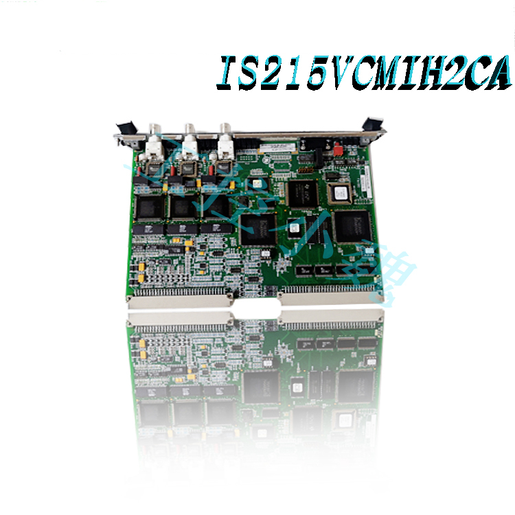
IS220PAICH2B – Analog I/O Module is available in stock which ships the same day.
IS220PAICH2B – Analog I/O Module comes in UNUSED as well as REBUILT condition.
To avail our best deals for IS220PAICH2B – Analog I/O Module, contact us and we will get back to you within 24 hours.
The IS220PAICH2B is an Analog I/O Module developed by GE. The module functions as an electrical interface between one or two Ethernet I/O networks and an input terminal board. The pack includes a processor board that is shared by all Mark VIe distributed I/O packs and an acquisition board dedicated to the analog input function. The pack can handle up to ten analog inputs, the first eight of which can be set to 5 V or 10 V inputs or 0-20 mA current loop inputs.
IS220PAICH2B Connectors
The following connectors are included in the pack:
A DC-37 pin connector on the I/O pack’s underside connects directly to the discrete input terminal board. The 24 input signals, ID signal, relay coil power, and feedback multiplex command are all housed on the connector.
The primary system interface is an RJ45 Ethernet connector labeled ENET1 on the pack’s side.
The redundant or secondary system interface is a second RJ45 Ethernet connector on the pack’s side labeled ENET2.
A 3-pin power connector on the pack’s side provides 28 V dc power to the pack and terminal board.
Processor
All of the logic required for the I/O pack to operate from one or two Ethernet inputs is contained in the processor application code. When two Ethernet inputs are used, both network paths are active at all times. A failure of either network will not disrupt the operation of the I/O pack or module, and the failure will be indicated by the working network connection. This configuration is more fault tolerant than a traditional hot-backup system, which uses the second port only when the primary port fails. The processor’s Ethernet ports auto-negotiate between 10 MB/s and 100 MB/s speeds, as well as between half-duplex and full-duplex operation.
Power Management
The 28 V input circuit of the I/O pack includes power management. Soft start is provided by the management function to control current inrush during power application. Following power application, the circuit implements a fast current limit function to prevent a pack or terminal board failure from propagating back onto the 28 V power system. The green PWR LED indicator will illuminate when power is present and functioning properly. When the current limit function is activated, the PWR LED will remain dark until the problem is resolved.
IS220PAICH2B Installation
Securely mount the terminal board of choice.
Insert the PAIC I/O pack directly into the terminal board connectors.
Use the threaded studs next to the Ethernet ports to mechanically secure the packs. The studs fit into a terminal board-specific mounting bracket. The bracket should be positioned so that no right-angle force is applied to the DC-37 pin connector between the pack and the terminal board. The adjustment should only be needed once during the product’s lifetime.
Depending on the system configuration, connect one or two Ethernet cables. The pack will work with either port. When using dual connections, it is common practice to connect ENET1 to the network associated with the R controller.
Connect the pack to power by plugging in the connector on the pack’s side. Because the I/O pack has inherent soft-start capability that controls current inrush on power application, it is not necessary to disconnect power from the cable before plugging it in.
Configure the I/O pack as needed using the ToolboxST application.
IS220PAICH2B Diagnostics
The I/O pack runs the self-diagnostic tests listed below:
A power-on self-test that includes RAM, flash memory, Ethernet ports, and the majority of the processor board hardware; and
Continuous monitoring of the internal power supplies for proper operation.
A check of the terminal board, acquisition board, and processor board electronic ID information to confirm that the hardware set matches, followed by a check that the application code loaded from flash memory is correct for the hardware set.
Hardware limit checking is performed on each analog input based on preset high and low levels near the end of the operating range. When this limit is reached, a logic signal is generated and the input is no longer scanned. L3DIAG xxxx is a logic signal that refers to the entire board.

System limit checking is performed on each input based on configurable high and low levels. These limits can be used to generate alarms, enable/disable devices, and as latching/non-latching switches. RESET SYS clears the out of bounds.
Precision reference voltages are included in each scan by the analog input hardware. The measured values are compared to the expected values to confirm the health of the analog to digital converter circuits.
A small burden resistor is used to sense the analog output current on the terminal board. The I/O pack conditions this signal and compares it to the commanded current to ensure the digital to analog converter circuits are in good working order.
The analog output suicide relay is constantly checked for consistency between the commanded state and the feedback indication. The ToolboxST application provides information on individual diagnostics. Individual diagnostic signals can be latched and then reset with the RESET DIA signal if they become healthy.
Frequently Asked Questions
What is IS220PAICH2B?
IS220PAICH2B is an Analog I/O Module developed by GE.
What is Noise suppression on inputs?
The ten circuits have a hardware filter with single pole down break at 500 rad/sec.
What is the Input converter resolution of the board?
The component comprises of 16-bit analog-to-digital converter
Recommended warehouse spare parts:


-1.jpg)
-1.jpg)

-1-100x100.jpg)
-1-100x100.jpg)
-300x300.jpg)
-300x300.jpg)

Reviews
There are no reviews yet.