Description
Product Description
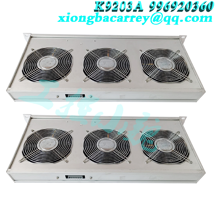
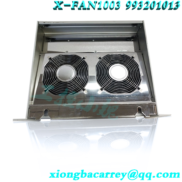
The X-SB 01 system bus module is used for the Programmable Electronic System (PES) HIMax. The module can only be inserted into slots 1 and 2 of the substrate. If the substrate contains only one module, the HIMax system uses only one module to run the system bus (mono operation). If the substrate contains two modules, the HIMax system uses two redundant system buses for operation (redundant operation). HIMA recommends using redundant operations (default) to leverage HMax system availability. This module has the following functions: establishing connections between modules. Establish connections with other substrates. Manage the rack ID and SRS of the module. In addition, this module provides an interface to programming and debugging tools (PADT). This module has passed TOV certification and is suitable for safety related applications below SIL 3 (IEC 61508, IEC 61511, and IEC 62061), category. 4 (EN 954-1) and PL e (EN ISO 13849-1). For more information on standards, please refer to the HIMax Safety Manual (HI 801 003 E) for testing and certification of modules and HIMax systems. Security function: This module transmits data through security related protocols. If the system bus fails, the redundant system ensures that the bus is connected to the bus, provided that both system buses are pre configured. The delivery scope module must be installed on a suitable connector board in order to operate. The integration of the connector board of this system bus module into the substrate is included in the delivery scope, see Chapter 3.6. When installing and disassembling modules to replace existing modules or installing new modules, please follow the instructions given in this chapter. When removing the module, the connector board remains in the HIMax substrate. This saves additional wiring workload for modules as all on-site terminals are connected through connector boards. This chapter explains how to install and remove the HIMax module. Modules can be installed and removed while the HIMax system is running. The notification module is jammed, causing damage to the bus and power socket! Failure to comply with this may damage the controller. Be careful when inserting the module into the backplane. Tools and Utilities ■ Screwdriver, slotted 0.8 x 4.0 mm Screwdriver, slotted 1.2 x 8.0 mm Installation 1. Open the cover plate on the fan frame: Move the lock to the open position. 1 Lft cover plate and insert into the fan rack. 2. Insert the top of the module into the hook in the track, see 1. 3. Rotate the lower edge of the module towards the substrate and gently press it to snap it into place, refer to 2. 4. Tighten the screws, refer to Section 3. 5. Pull the cover out of the fan bracket and close it. 6. Lock the cover plate. Move 1. Open the cover plate on the fan rack: The lock can be moved to the open position. Lift the cover and insert the fan frame 2. Loosen screws 3. 3. Rotate the lower edge of the module out of the substrate. Lift and apply the pressure of the light to remove the module from the hook rail, refer to 2 and 1. 4. Pull the cover out of the fan frame and close it. 5. Lock the cover plate.


.jpg)
-100x100.jpg)
Reviews
There are no reviews yet.