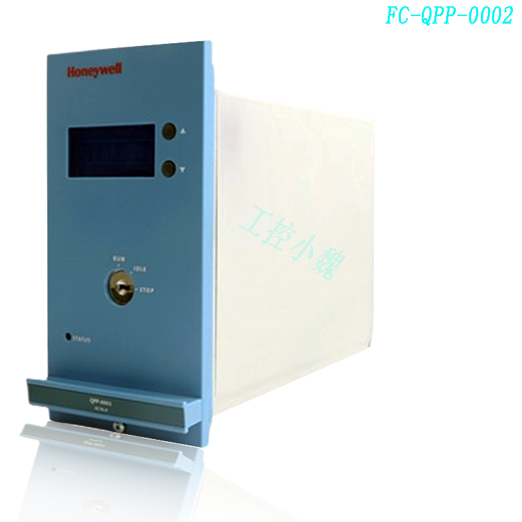
Description
Many products have not been listed yet. For more products, please contact us
If the product model is inconsistent with the displayed image, the model shall prevail. Please contact us for specific product images, and we will arrange for photos to be taken and confirmed in the warehouse
We have 16 shared warehouses worldwide, so sometimes it may take several hours to accurately return to you. We apologize for any inconvenience caused. Of course, we will respond to your concerns as soon as possible.
FC-SAI-1620M Other names:
Control System FC-SAI-1620M
FC-SAI-1620M processor module
Input controller FC-SAI-1620M
FC-SAI-1620M Editable Controller
IO configurations
Redundant IO configurations
Redundant IO configurations can be used in Safety Manager with a redundant Controller. In this fully redundant configuration, each Control Processor has its own IO system to which it has exclusive access.
Each Control Processor reads its own input interfaces once every program cycle. After input matching, both Control Processors execute the user-defined control program and update their output interfaces according to the results. Before setting, the Control Processors compare the calculated output results to ensure identical operation.
Redundant IO configurations are typically used for safety functions that require optimal availability.
With Safety Manager R120, also Analog Outputs can be used in a redundant topology.
Non-redundant IO configurations
Non-redundant IO configurations can be used in systems with a non-redundant Controller as well as in systems with redundant Controller.
Fully non-redundant systems are typically used for safety applications where redundancy is part of the process.
In a Safety Manager setup with a redundant Controller, and (partly) nonredundant IO, both Control Processors alternately assume responsibility for the non-redundant IO interfaces. This ensures both Control Processors can always access the IO interfaces correctly.
Safety Manager configurations with a redundant Controller and non-redundant IO interfaces are typically used for safety critical applications with increased demands for system availability, for example because of redundancy in plant equipment..jpg)
The combination of redundant and non-redundant IO interfaces is extremely powerful. Process safeguarding functions requiring optimal availability are controlled through the redundant IO interfaces, and less demanding safety functions through the non-redundant IO interfaces.
On-Line Modification
On-Line Modification (OLM) is a TÜV-approved Safety Manager™ option that is supported by Safety Manager configurations with redundant Controller. It enables modification of the application software, system software and Safety Manager hardware configuration, while maintaining the system’s critical control function for the operational plant. This means that the system can be upgraded without the need of a plant shutdown. During on-line modification, the changes are carried out in one Control Processor at a time. Meanwhile, the other Control Processor continues to monitor the process. The system will always perform a compatibility check across the control program in order to guarantee a safe changeover from the old control function to the new one. It will also report the numbers of the functional logic diagrams (FLDs) that have been changed, which complies with the ‘verification requirements’ of IEC 61508 and ANSI/ISA S84.01.
Hot-swap of Safety Manager Controller Modules
The user is able to exchange “not safety-related” Safety Manager Controller modules while the Safety Manager Controller continues operation. The communication module type USI-0001 and the battery and key switch module type BKM-0001 can be swapped on-line without stopping the affected control processor
Self Educating Safety Manager Controller Modules
If required, the user can replace the QPP-0001, QPP-0002 and / or the USI-0001 with a spare module. If the other control processor is running, the spare modules inserted will automatically be updated with all the software (including embedded software), which is already used in the running Control Processor. Note: If the controller number in the spare QPP is equal to the already running controller number, the update will not take place: reset the controller number first.
Power System
Reliability of process data depends on the reliability of all related hardware of the process loop, i.e. sensing device, IO wiring, IO channel hardware and the required power supply voltages. Where possible, Safety Manager™ provides the supply power to the electronics of the entire loop, including the field instrumentation. The result is a fully integrated solution for reliable (safety) data gathering and related safeguarding actions, with the following advanced features:
Electronically short-circuit proof,
Loop-monitoring for short-circuiting and lead breakage, and
Checking of the operational band of analog transmitters.
Where other systems require linkage of several externally mounted parts to establish the entire data collection chain, Safety Manager solution offers the fully integrated and tested loop approach as demanded by IEC 61508 and ANSI/ISA S84.01.
Write Protection
To maintain safe and reliable operation of Safety Manager™, the system does not allow direct write access to its hardwired IO via communication links. Write requests, which are received via the Universal Safety Interface (USI) (serial and or Ethernet communication), are passed on to the Safety Manager control program via dedicated boolean and numerical inputs. The inputs appear in the input area of the Functional Logic Diagrams, where the conditions for write access have been defined..jpg)
IO Signal Forcing
For maintenance reasons, it may be desirable to force an input or an output signal to a certain fixed state, e.g. when exchanging a defective input sensor. This allows the sensor to be exchanged without affecting the continuation of the production. During the exchange, the applicable input is forced to its normal operational state. While being desirable in some situations, forcing a signal to a specific, fixed value may also create a potentially hazardous condition.
Safety Manager™ provides a force function which supports maintenance personnel in applying forces consciously. It only allows forcing of signals that were specifically selected during the system design. During operation, the system is protected against unauthorized forces via a key switch. Forcing of Safety Manager signals is only possible via Safety Builder, using a passwordprotected software function. All forcing actions are included in Safety Manager event reports for trace ability purposes.
Serial Communication with Process Computer Systems
Safety Manager supports the exchange of application and diagnostic data with DCS systems or other equipment via serial communication links, using the nonproprietary Modbus RTU communication protocol. All point data available within the Safety Manager application can be made available via Modbus RTU Data written to the Safety Manager Controller via Modbus RTU is available in the Safety Manager application via digital and numerical input variables, which allow the user to define the conditions of use in the safety application.
All products on this website are special products, and market prices have been fluctuating,
The specific customer service quotation shall prevail, as the product is a new product and the price is not genuine,
Please confirm the model, product, price, and other detailed information with customer service before placing an order. The website has been used,
The new one is for sale, please contact customer service to communicate.
Recommended goods in the warehouse:
FC-SCNT02
FC-SCNT01
FC-USI-0002
FC-PSU-UNI2450U V2.1
FC-PSU-240516
FC-PSU-UNI2450U V1.0
FC-SAI-1620M
FC-SAI-1620M V1.4
FC-SDO-0824 V1.3
More……


-100x100.jpg)
-100x100.jpg)

Elbert Linders –
Wow that was strange. I just wrote an really long comment but after I clicked submit my comment didn’t show up. Grrrr… well I’m not writing all that over again. Regardless, just wanted to say wonderful blog!