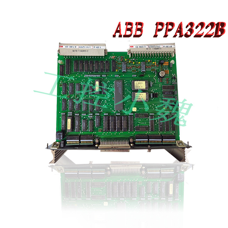
Description
Vibro-meter VM600 series vibration cards
The Chromalox 2104 1/4 DIN temperature and process controller is a low-cost, high-performance, single-loop controller that can be used for temperature, flow, pressure and level control applications. With universal sensor inputs and front panel operator setup, one 2104 controller can be easily field configured for a wide variety of applications, and simply reconfigured as application needs change. This makes it an exceptional choice for OEMs with multiple control needs, manufacturing facilities, testing facilities and testing applications.
Model Identification Before installation, please identify your controller model number. The model number is written on the tag on the side of the housing.Microprocessor-based 1/4 DIN Temperature Controller. Universal Sensor Input accepts Thermocouple, RTD, Current or Voltage Inputs. PID, ON/OFF with Fuzzy Logic Control Capability. One Digital Input and Analog Remote Set Point.RO Output #1 Single Output Control Relay/SSR Drive (jumper selectable) Relay—N.O. Form A Contact, 1A at 120 or 230 Vac SSR Drive—24Vdc at 40mA TO Triac—1 Amp at 120 or 230 Vac AO Analog—4-20mA or 1-5 Vdc, non-isolated On receipt of your 2104 controller, immediately make note of any visible damage to the shipment packaging and record this damage on the shipping documents. Unpack the controller and carefully inspect it for obvious damage due to shipment. If any damage has occurred, YOU must file a claim with the transporter,

as they will not accept a claim from the shipper. If the controller will not be immediately installed and placed into operation, it should be stored in a cool, dry environment in its original protective packaging until time for installation and operation. Temperature extremes and excessive moisture can damage the instrument.The 2104 has up to seven (7) hardware switches located on the bottom of the controller. The switches are accessible through cutouts in the controller housing and do not require that you remove the controller from its housing to access the switches. Figure 2.1 identifies the switches. Instructions for switch settings are given in the corresponding sections of the manual Sensor selection requires that you: 1. Set the sensor switches for the correct sensor type. 2. Program the input sensor type in sensor selection setup on the INPT Page (see page 36). It is much easier to set the sensor input switches before you mount and wire the controller. To set the sensor switches: 1. Locate the sensor switches—#1, #2 and #3— on the bottom of the controller, as shown in Figure 2.1 on the previous page. 2. Place the switches in the appropriate Up or Down position for your input type: Switch # Input Type 1 2 3 T/C Up Up Up RTD Down Up Up 4-20mA Up Down Down 1-5 Vdc Up Up Down Figure 2.2, on the following page, shows the mounting dimensions for the controller: 1. Cut out the square “panel cutout” mounting hole and install the unit as shown in Figure 2.3. 2. Place the controller through the square panel cutout and replace the mounting clip. 3. Tighten the mounting clip screw (do not over- tighten) to secure the controller firmly against the mounting surface.Good Wiring Practices 1. When planning the system wiring, separate wiring into functionally similar bundles – i.e., power leads, sensor leads, output signal lines, etc. If the power leads and sensor leads must cross, they should cross at a 90° angle to each other (perpendicular). 2. Locate all sources of electrical noise in your system, and separate these sources from the control systems— motors, contacts, solenoids, etc. Electrical noise can affect the function of any control system. When driving a contactor coil or other inductive load, an appropriately rated AC snubber circuit is recommended (Chromalox Part. No. 0149-01305),
.jpg)
as described on page 11, “Relay Output Wiring.” 3. For sensor wiring practices, see Sensor Wiring Notes, next page. 4. Additional information on good wiring practices is available from IEEE, 345 East 47th St., NY, NY 10017. Request IEEE Standard No. 518-1982. Wiring Instructions Make all electrical wiring connections to the back of the controller before power is applied to the unit. All wiring must comply with local codes, regulations and ordinances. This instrument is intended for panel mounting and the terminals must be enclosed within a panel. Use National Electric Code (NEC) Class 1 wiring for all terminals except the sensor terminals. Check the wiring decal on the side of the unit to verify the model number. The wiring decal shows the wiring terminations. All wires will be connected to the terminals on the back of the instrument case. Specific wiring instructions for different input and output types are given in this section.Sensor Input Wiring Sensor Input Wiring Notes: •Sensor leads (thermocouple and RTD) should not be run together in the same conduit as power wiring. •Twisted pair, shielded wire is recommended for sensor connections. •False process readings can occur if the sensor wire is exposed to electrical noise. •Ungrounded thermocouples are recommended. •If thermocouple extension wire is required, it must be the same type as the thermocouple (i.e., if a Type K thermocouple is used, then Type K extension wire must be used). •Thermocouple wires should connect directly to the controller terminals. Do not use copper crimp terminals or solder terminals to make connections. •If shielded thermocouple wire is used, the shield must be grounded at one end only, preferably at the shield ground terminal on the controller, as shown in Figure 2.5. •Three wire RTDs are recommended for greatest accuracy. •Standard shielded copper wire is recommended for RTD extensions.Self-Tuning The 2104 tuning algorithm establishes PID constants (PBL, ARL, RATL) that will bring the process to setpoint as quickly as possible with little overshoot. Tuning can be performed at powerup (CTRL PAGE, TUNE = PRUP) or can be initiated immediately (CTRL PAGE, TUNE = BEGN). When tuning, the 2104 will flash “TUNE” in the lower display. If the process variable is not at least 50°F (28°C) away from setpoint, the 2104 will turn off the control output until the process temperature is 50°F from setpoint. If the 50°F temperature difference is not reached within 30 minutes, “TERR” will be displayed, indicating that tuning was not successful (tuning error). Press RESET to clear “TERR”. After successfully tuning, tuning is turned OFF in the tuning menu (TUNE). Heat/Cool Self-Tuning For heat/cool control applications, when the cooling medium is specified (PAGE CTRL, COOL = AIR, H2O, OIL), both heat (PID1) and cool (PID2) parameters are computed during a heat tune (tuning is invoked while the process temperature is at least 50°F below setpoint). If no cooling medium is specified (PAGE CTRL, COOL = PID2) the PID2 parameters (PB2, AR2, RAT2) will not change during a self-tune. A cool tune (tuning is invoked while the process temperature is at least 50°F above setpoint) will compute PID parameters for cooling only. One way to initiate a cool tune is to first heat tune, then lower the setpoint by 50°F (28°C) and initiate selftuning for cooling (CTRL PAGE, TUNE = BEGN). A cool tune will change PID2 settings if Heat/Cool control is selected for the control type (CTRL PAGE, CONT HTCL).
Model recommendation:

-100x100.jpg)

Reviews
There are no reviews yet.