Description
IS200EMIOH1AFB – CARD-EX2100 MAIN I/O is available in stock which ships the same day.
IS200EMIOH1AFB – CARD-EX2100 MAIN I/O comes in UNUSED as well as REBUILT condition.
To avail our best deals for IS200EMIOH1AFB – CARD-EX2100 MAIN I/O, contact us and we will get back to you within 24 hours.
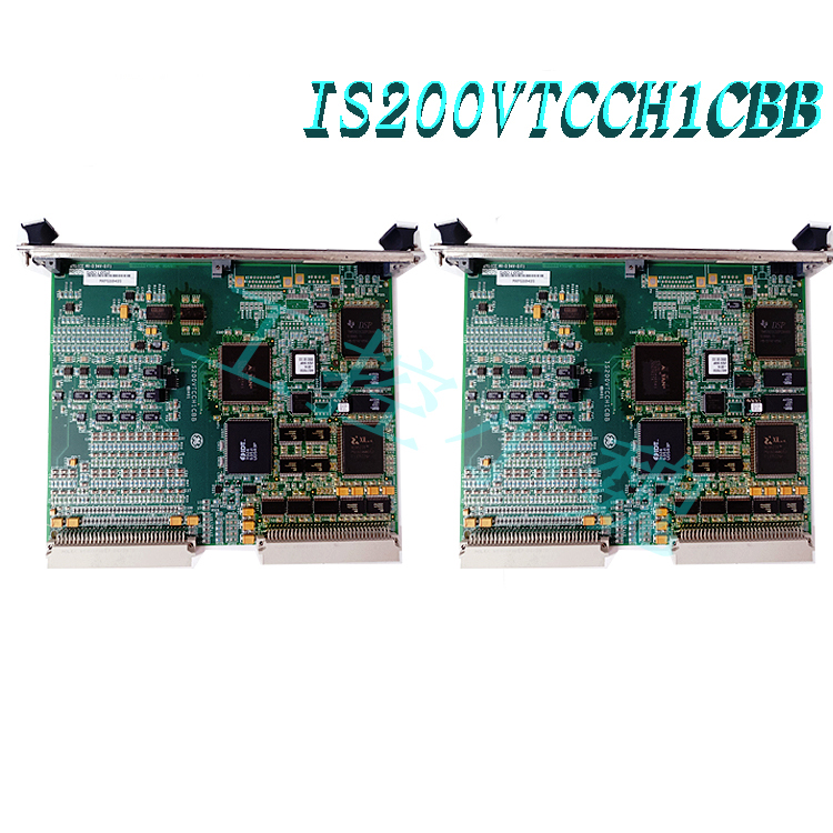
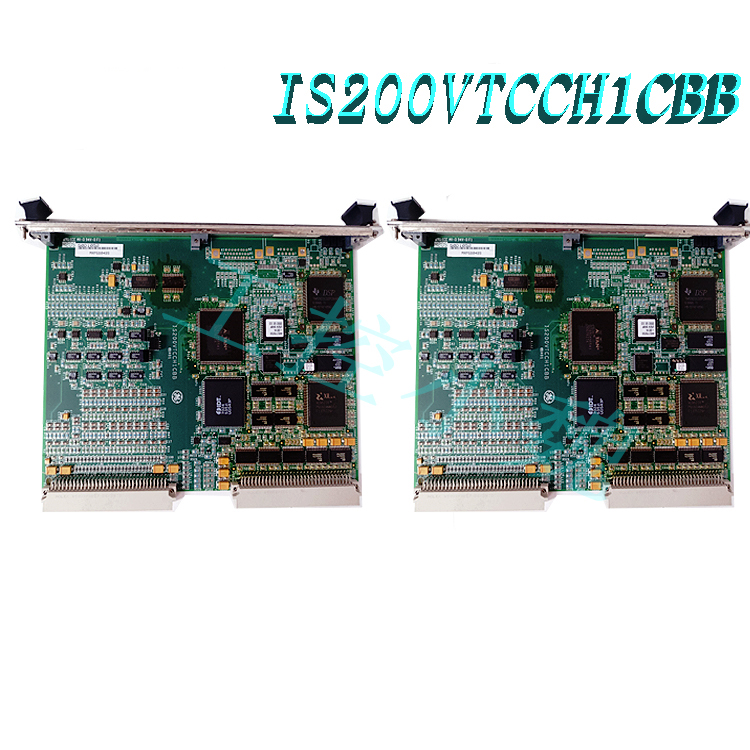
Exciter Main I/O Board part IS200EMIOH1A is from the EX2100 series. This board manages the I/O from several other terminal boards and has PT and CT signals. One of the primary functions is to send gate pulse signals over the backplane to the ESEL and then the EGPA.
Product Description
The primary function of the Exciter Main Input/Out IS200EMIOH1A board is to manage all of the inputs/outputs from the ECTB, EACF, EXTB, and EPCT terminal boards. This board is a double-height-versa module Eurocard and is also single-slotted. Another primary function of the IS200EMIOH1A is to send gate pulse signals from the backplane to the ESEL board, after the signals have been received by the ESEL board the signals will then be sent to the EGPA board which is located in the power conversion cabinet.

When controlling the inputs and outputs of other terminal boards, the IS200EMIOH1A will control contact inputs, pilot trip relay drivers, PT and CT signals, and output relay drivers. As the EMIO board connects to the EXTB board the EMIO board will initiate de-excitation, which means that the EMIO board also controls the EDEX board that the EXTB is connected to.
When using the IS200EMIOH1A board the best manual to use is the GEI-100453 IS200EMIO Exciter Main I/O Board manual, but as that manual is difficult to find, the GEH-6632 EX2100 Excitation Control User’s Guide has information related to the EMIO board on page forty-eight.
Frequently Asked Questions about IS200EMIOH1A
If the EX2100 Controllers are being used in simplex system mode what will the IS200EMIOH1A do?
If the EX2100 Controllers are operating in simplex mode then the voltage signals will be sent through the J305 connector. Once the signals have been sent through the J305 connector they will be sent to the EMIO board in the M1 Controller.
-1.jpg)
The IS200EMIOH1A board controls the 53A and 53A field flashing relays, this function is done so through the drivers on the EMIO board.
What parts of the EBKP Backplane is the IS200EMIOH1A model connected to?
The IS200EMIOH1A board is connected to Section C as well as the M1 and M2 Controllers.
The EPCT board provides an analog input for customer use, how does the IS200EMIOH1A board interact with this function?
When the EPCT board is used for providing analog inputs the EMIO board will sample the input at 2000 samples per second, the accuracy when this occurs is better than 1% full scale.
Reviews For IS200EMIOH1A
The IS200EMIOH1A board controls many of the terminal boards within the EX2100 series through PT and CT currents along with many other input/output functions.
Popular model recommendations:
IS230TSPRH1C
IS200TPROS1CBB IS230TSPRH1C
IS200TPROS1CBB IS230TSPRH1
IS200TREAH2AED IS230TNEAH2A
IS200TTURH1CFD IS230TNTRH1C
IS200TVBAH2ACC IS230TVBAH2A
IS200TVBAH2ACC
IS230SNCIH6A
IS230SNIDH1A MRP689579
IS230SNRTH2A
BENDER SERIE-360-IRDA365-4
ABB Central Processing Unit 3BHE041465P201
ABB Central Processing Unit UDD406A 3BHE041465P201
IS420ESWAH5A
IS420ESWAH4A
IS420PPNGH1A
IS420UCSBH4A
IS420UCSBH1A
more……


.jpg)
.jpg)

-100x100.jpg)
-100x100.jpg)
-300x300.jpg)
-300x300.jpg)
admin –
The primary function of the Exciter Main Input/Out IS200EMIOH1A board is to manage all of the inputs/outputs from the ECTB, EACF, EXTB, and EPCT terminal boards. This board is a double-height-versa module Eurocard and is also single-slotted. Another primary function of the IS200EMIOH1A is to send gate pulse signals from the backplane to the ESEL board, after the signals have been received by the ESEL board the signals will then be sent to the EGPA board which is located in the power conversion cabinet.