-1-100x100.jpg)
-1-100x100.jpg)
Description
IS200JPDSG1A – Distribution board in stock, shipped on the same day.
IS200JPDSG1A – The distribution board is in an unused and rebuilt state.
If you want to get the best discount on IS200JPDSG1A – Distribution Board, please contact us and we will reply to you within 24 hours.
IS200JPDSG1A Other names:
PCB module IS200JPDSG1A
IS200JPDSG1A Input/Output Module
Analog module IS200JPDSG1A
IS200JPDSG1A controller spare parts
Product Description
IS200JPDSG1A is a distribution board used in GE turbine control systems. The functional abbreviation of IS200JPDSG1A in GE documentation is “JPDS”.
IS200JPDSG1A is equipped with two terminal blocks, each with five screws. These terminal blocks are labeled as PR, PS, PT, N, and N. The wiring board is used for daisy chain connection of distribution boards. The board has two 50 pin ribbon connectors, labeled as P1 and P2. These ribbon connectors are used to transmit feedback signals between boards. This board has a female connector labeled JA1. This is a DC-62 connector that is compatible with I/O packages on IS220PPDA. The other connectors on the board include seven 2-position plugs, six 6-position plugs, and three 9-position plugs.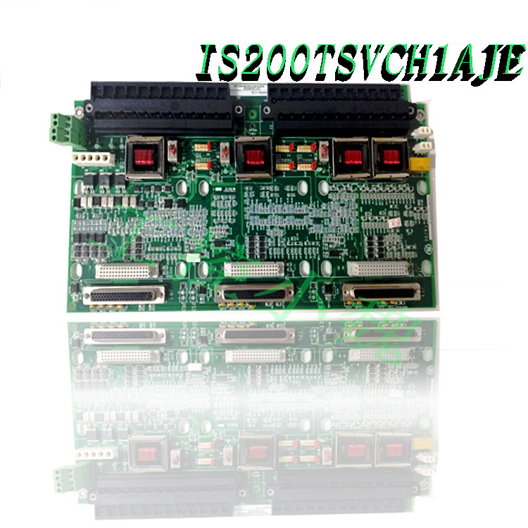
IS200JPDSG1A is equipped with three inductor coils, four varistors, four TP test points, two transistors, and multiple resistors and capacitors. Each TP test point has a series connected 10k resistor for isolating the loop. This board is designed for DIN rail installation and can be installed next to other distribution boards. IS200JPDSG1A drilled holes at six locations. The GEI-100613 released by GE will provide more information on the operation, wiring, and installation of this board.
Function Description
IS200JPDSG1A is a 28 V distribution board manufactured and designed by General Electric. It is part of the Mark VIe series used in distributed control systems. The 28 V Power Distribution (JPDS) board provides 28 V DC input power to the control system from external AC/DC or DC/DC converters. JPDS integrates feedback from PPDA I/O packages into the PDM system.
Compatibility
The JPDB, JPDF, and JPDE feedback signals P1/P2 on the board can be connected to create PPDA I/O packets.-1.jpg)
This I/O package is compatible with the DC-62 connector on JPDS.
Installation
The board is designed to be easily installed on a metal bracket, which can be mounted on vertical DIN rails and is usually placed side by side with other distribution boards. JPDS can also choose to be equipped with metal brackets customized specifically for direct installation.
Grounding
The top and bottom of the board are equipped with 50 pin diagnostic connectors. The grounding of the board is established through a metal plate bracket, which is connected to the lower back base, usually the system FE (functional grounding).
Physical layout
In terms of its physical layout, the JPDS board receives power from the cables and effectively distributes it to JR, JS, and JT connectors. When carrying PPDA I/O packages, the installation of JPDS is ideal to ensure that the indicator lights on the package are clearly visible. If two JPDS boards are used together, they should be placed in a location that is easy to access for any terminal board connection. However, the precise position of JPDS within the panel is not important.
Connectors P1 and P2 play a crucial role in transmitting feedback signals: P1 transmits the feedback signal to the circuit board carrying the PPDA I/O package, while P2 receives feedback from other distribution boards and routes these signals from P1 to PPDA. When planning the feedback cable connection from JPDS P2 to another distribution board, careful consideration should be given to the routing of the feedback cable.
Application Description
Internally, wiring allows for the maintenance of three independent 28 V DC power buses or the merging of these three buses into one internal bus. Each individual bus is designed to handle currents up to 25A, sharing a common ground with a rated current of 75A. Three power supplies can be used to operate the R, S, and T controllers and their I/O from a separate power source. A failure of one power supply will only affect one controller and its I/O, and will not affect the other two channels.
To ensure uninterrupted power system feedback in the event of channel power failure, a dedicated 28 V diode or power output is specifically equipped for the PPDA I/O package. Alternatively, the board provides a configuration involving jumpers between the R, S, and T 28 V bus connection screws on TB1 and TB2, thereby establishing a single highly reliable 28 V power supply.
In addition, screw terminals can be used to parallel the power buses of two adjacent JPDS boards, providing functions such as control rack output for duplex or TMR applications, increased JPDP output, and the ability to provide power redundancy for separate R, S, and T power supplies through two input power supplies on each bus.
In specific applications, the battery bus can be used as a power backup. Using a grounded battery system as input to this board requires adding additional diodes outside the JPDS to ensure isolation between the battery and the internal bus.
Surgery
The power distribution board (JPDS) transfers 28 V DC power from the selected power source to the JPDP board (used to power the I/O pack) and control rack. The JR, JS, and JT connectors are used to provide traditional 28 V power input for JPDS.
JR, JS, and JT are three 28 V power input connectors. There are two positive connections and three negative connections on the power connector. There are also three healthy power inputs, each with two dry contact inputs; These signals are used as diagnostic signals.
The J1, J2, J3, J4, J5, and J6 six pin connectors provide six outputs for the JPDP card (3×2 Mate-N-Lok). The pin allocation on this connector matches exactly with the pin allocation on JPDP. To power the I/O pack, JPDS can be directly connected to up to six JPDL boards.
Three output JARs, JAS, and JAT each have a common mode choke for noise reduction and a positive temperature coefficient fuse for limiting current.-1.jpg)
By utilizing the independent screw terminals on TB1 and TB2, an internal 28 V bus can be connected at the top and bottom of the circuit board. R. The maximum continuous current capacity of the S and T screw terminals is 35 A. You can use these terminals to connect the circuit board together. For grounding, specify the use of 75 A screw terminals.
PPDA power diagnostic I/O package DC-62 connection. The 50 pin diagnostic ribbon cable connecting JPDS to PPDA allows PPDA to monitor JPDS and up to five additional distribution boards.
Frequently asked questions
What is IS200JPDSG1A?
This is a 28 V distribution board manufactured and designed by General Electric
How can JPDS be integrated into PDM systems?
The board provides feedback through PPDA I/O packages and seamlessly integrates into the PDM (power distribution module) system. This integration allows for comprehensive monitoring and control within the system.
What feedback signal connectors are compatible with this board?
It is compatible with P1/P2 connectors on JPDB, JPDF, and JPDE, all of which lead to PPDA I/O packages. This compatibility ensures smooth communication and feedback exchange between JPDS and specified components in the system.
How compatible is the DC-62 connector on JPDS?
The DC-62 connector on the board is particularly compatible with the I/O package. This compatibility helps to directly and efficiently connect JPDS boards and I/O packages, thereby enhancing functionality and communication.
All products on this website are special products, and market prices have been fluctuating,
The specific customer service quotation shall prevail, as the product is a new product and the price is not genuine,
Please confirm the model, product, price, and other detailed information with customer service before placing an order. The website has been used,
The new one is for sale, please contact customer service to communicate.
Model recommendation:
IS220PPDAH1A
IS411JPDHG1A
IS210JPDHG1A
IS4210UCSBH4A
IS42yYDASS1A
IS40ySSUPS1A
IS220YSILS1B
IS200SCSAS1A
IS200WCSAS1A
IS220YSILS1A
more……
-300x300.jpg)
Reviews
There are no reviews yet.