Description
IS200SHRAS2A- Relay output terminal board in stock, shipped on the same day.
IS200SHRAS2A- The relay output terminal board is in an unused and rebuilt state.
If you need the best discount on IS200SHRAS2A- Relay Output Terminal Board, please contact us and we will reply to you within 24 hours.
IS200SHRAS2A Other names:
PCB module IS200SHRAS2A
IS200SHRAS2A interface board
Input/output board IS200SHRAS2A
Function Description
IS200SHRAS2A is a relay output terminal board manufactured and designed by General Electric, and is part of Mark VIeS for distributed control systems. The TRLYS1F relay output terminal board with TMR contact voting provides twelve relay outputs with contact voting. There are a total of 36 sealed relays on the board, with 12 for each TMR segment. When paired with TRLYS1F or TRLYS2F, relays from R, S, and T are connected to output B-type (NC) voting or A-type (NO) voting contacts. You can apply 115 V AC or 24/125 V DC power. TRLYS F board does not support simplex applications and distribution. Conventional 125 V DC or 115 V AC, as well as optional 24 V DC with independent fuses, can be installed as distribution board options to provide on-site solenoid valve power. For AC applications that do not require a fuse in the neutral circuit (pin 3 of J1-J4), it provides a fuse on the high voltage side of each distribution circuit (pin 1 of J1-J4).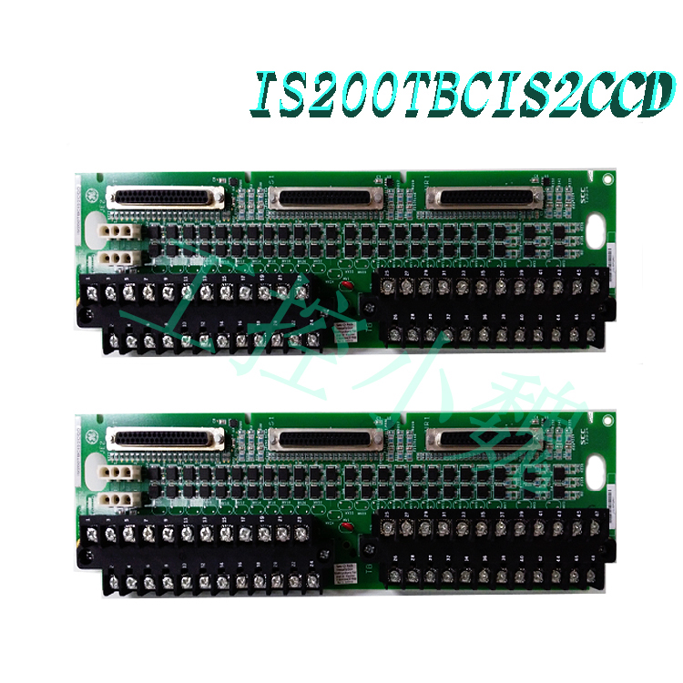
When the diagnostic message indicates that TRLY # F is involved in one of them, it should be considered as the lowest replaceable unit (LRU) and replaced as a set to simplify troubleshooting for this highly interactive circuit board group and shorten the average repair time. Gold circuit boards or previously known reliable circuit boards can be used to match specific suspicious circuit boards, in order to further isolate faulty individual circuit boards when necessary and when time and environment permit.
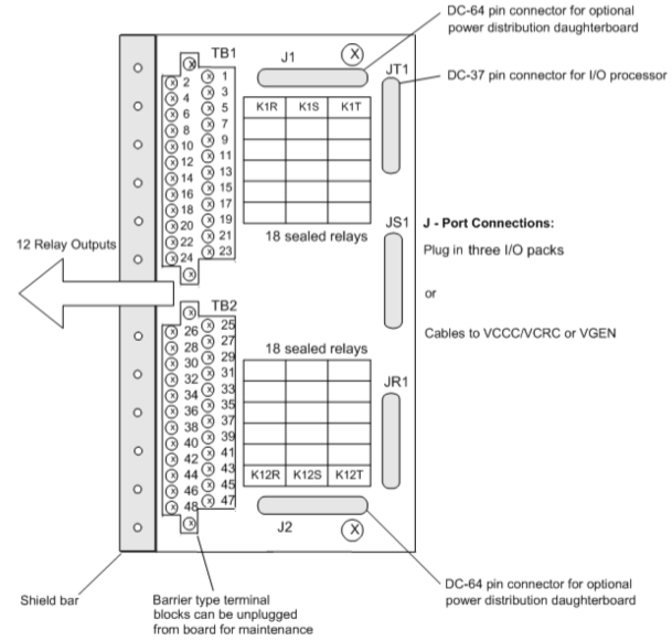
Compatibility:
TMR application is the only supported application for TRLY 1F and TRLY 2F terminal boards. The JR1, JS1, and JT1 37 pin D-type connectors on the terminal board can accept three TMR I/O packages.

Installation:
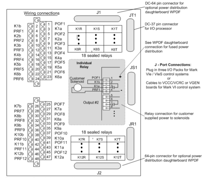
Connect the wires of the 12 solenoids directly to the two I/O terminal blocks on the terminal block. Each terminal block has 24 terminals that can accommodate up to # 12 AWG wires and are secured with two screws. Each terminal block includes a shielded termination strip that is directly connected to the chassis ground on the left side. If a WPDF sub board is installed, provide solenoid power for outputs 1 to 12. The customer’s power supply can also be connected to the wiring board as an alternative solution. The three I/O packages connected at JR1, JS1, and JT1 provide 28 V DC power to the terminal block relay coils and electronic devices.
Surgery:
The three I/O packages connected at JR1, JS1, and JT1 provide 28 V DC power to the terminal board relay coils and electronic devices. Both AC and DC voltages are handled by the same relay. The various circuits on the TRLY # F terminal board use the same relay.
The relay is driven at frame rate by a relay driver installed on TRLY # F. The relay output has a fault safety function. If the cable is unplugged or communication with the relevant I/O package is lost, a vote is made to cut off the power supply to the relevant relay..jpg)
This board does not support other applications. Plug JR1, JS1, and JT1 are used to connect three I/O packets R, S, and T to TRLY # F, and relay control signals are routed from the three I/O packets to TRLY # F. Each TMR segment R, S, and T is directly controlled by corresponding signals. The I/O package of each section only provides power to the relay coil of that section and does not share power with other sections.
TRLY # F has TMR contact voting. Relay contacts from R, S, and T are coupled to provide A-type (NO) contacts or B-type (NC) outputs through TRLY 1F and TRLY 2F, respectively. You can use 115 V AC or 24/125 V DC. The TMR voting contact circuit is shown in the attached diagram.

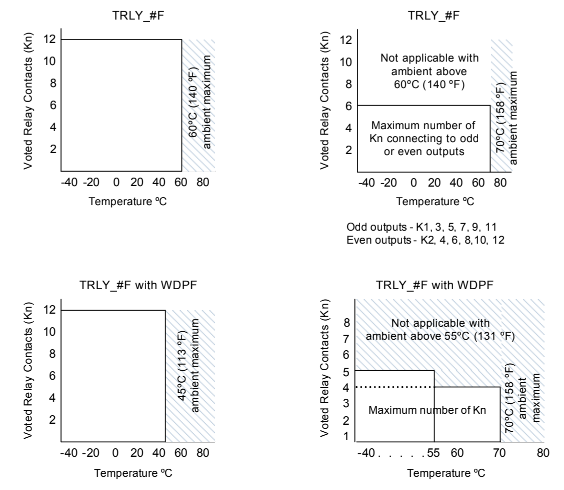
The following figure shows how the number of voting contact output channels varies in a zigzag pattern based on the maximum ambient temperature.
Diagnosis:
At frame rate, the voltage of each relay coil is monitored and compared with commands. If there are five consecutive frames that are inconsistent, the alarm will be locked.
The voltage of each solenoid power supply will be tracked, and an alarm will sound if the voltage drops below 16 V AC/DC.
If any output becomes abnormal, a composite diagnostic alarm L3DIAG XXXX will be triggered..jpg)
The I/O package will query the unique ID device for each terminal board connector. The read-only chip also includes the serial number, board type, revision number, and the location of the JR1/JS1/JT1 connector, and is encoded with the connector ID. When the I/O package reads the ID chip and encounters a mismatch, it will generate a hardware incompatibility fault.
Frequently asked questions
What is GE Mark VIeS IS200SHRAS2A?
IS200SHRAS2A is a relay output terminal board used in distributed control systems.
How are the circuit boards shipped from Xiamen Xiongba packaged?
Place the parts in the anti-static bag and safely pack them in the ESD box with ESD foam to protect the electrical components.
How to check the price and supply situation of IS200SHRAS2A?
Please contact Carrey, the Industrial Control Sales Consultant, for sales (phone number:+86 18030177759) or request a quotation.
All products on this website are special products, and market prices have been fluctuating,
The specific customer service quotation shall prevail, as the product is a new product and the price is not genuine,
Please confirm the model, product, price, and other detailed information with customer service before placing an order. The website has been used,
The new one is for sale, please contact customer service to communicate.
Model recommendation:
IS220YDOAS1A
IS40yTBCIS3C
IS40ySTCIS4A
ISx0yTBCIS2C
ISx0ySTCIS2A
ISx0ySTCIS1A
IS400STCIS2A
IS400STCIS1A
IS200TBCIS2C
IS200AEPAH1BKE
More……


-100x100.jpg)
-100x100.jpg)
-300x300.jpg)
-300x300.jpg)
Reviews
There are no reviews yet.