-100x100.jpg)
-100x100.jpg)
Description
Many products are not yet on the shelves. Please contact us for more products.
If the product model is inconsistent with the display picture, the model shall prevail. Please contact us for specific product pictures, and we will arrange to take photos in the warehouse for confirmation.
We have 76 shared warehouses around the world, so sometimes it may take several hours to return to you accurately, please understand. Of course, we will respond to your concerns as soon as possible.
Functional Description
The IS200TTURH1CFD is a turbine-specific primary trip board developed by GE. It is part of the Mark VI control system. The primary turbine protection input terminal board is an important component that interfaces with the VTUR module and helps to achieve comprehensive turbine protection functions. PTURH1A is compatible with the turbine terminal board TTURH1C and STUR boards, but is not compatible with DIN rail mounted DTUR or other TTUR boards. And is a member of the Mark VIe series of turbine control systems and turbine control system components. This IS200TTURH1CFD printed circuit board (PCB for short) is actually a modified version of another GE PCB; namely, IS200TTURH1, and a major C-level functional revision, a minor F-level functional revision, and a single artwork revision of D-level have been added. This IS200TTURH1CFD board is specially designed by GE Industrial Systems (a subsidiary manufacturer of GE responsible for the mass production of all products of the Mark VIe turbine control system series).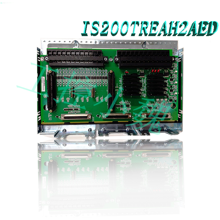
Hardware Tips and Specifications
This IS200TTURH1CFD Terminal Turbine Board features a series of unique and individual hardware components, and like any general purpose electrical printed circuit board, these hardware elements are most easily understood when combined with the functionality of the board to which they belong. The primary intended function of this IS200TTURH1CFD Terminal Turbine Board is to act as a terminal for a series of 48 input/output connections that are essential to the functionality of its larger VTUR Turbine Control Board assembly. Other functions of this TTUR abbreviation product include its role as a controller for the 52G Main Breaker Relay Coil of the aforementioned VTUR assembly.
Now that some of the basic functions of this IS200TTURH1CFD board have been described, its product-specific hardware contents can be further explored. First, this TTUR Terminal Turbine Board does not utilize any special assembly revisions, as evidenced by the normal IS200 series labeling of its IS200TTURH1CFD product number. While this is true, it is important to note that this board utilizes three significant product revisions, including the special F-class second functional revision. Two key hardware elements immediately visible on this IS200TTURH1CFD product baseboard are its two pluggable terminal blocks, which have been attached to the TTUR baseboard using two screws per terminal block for ease of maintenance. These terminal blocks accept a total of 24 I/O connections per terminal block; obviously core to the specification functionality of this board. In addition to the terminal blocks that are critical to the configuration of this IS200TTURH1CFD board, a number of other important hardware components are present, including:.jpg)
Six connector ports with name labels
Shielding strip extends to the left side of this PCB
TTL speed sensor wiring
Factory drilled holes for mounting
Conformal type of PCB protective coating
Input and output configuration
Passive pulse rate devices: The PTTUR accommodates 12 passive pulse rate devices that are strategically placed to sense the gears for accurate measurement of turbine speed. This input is critical for monitoring turbine rotational dynamics.
Voltage signals: The board effectively captures generator voltage and bus voltage signals transmitted from the voltage transformer. These voltage readings are critical in assessing the electrical health and performance of the turbine and associated systems.
125 V DC Output: The PTTUR features a dedicated 125 V DC output channel designed to power the main breaker coil for automatic generator synchronization. This feature improves operating efficiency and system reliability during synchronization.
Shaft Voltage and Current Sensors: The PTTUR carefully processes inputs from shaft voltage and current sensors to measure induced shaft voltage and current. These measurements provide insight into the mechanical and electrical condition of the turbine components.
Relay Configuration
K25 Relay: This relay closes in conjunction with the K25P and K25A to provide the 125 V DC power required to engage the main breaker (denoted as 52G). This fail-safe mechanism improves system reliability and safety.
Connector Configuration
In the standard configuration, the speed signal line is connected to the VTUR via the JR5 connector, while other critical signals use the JR1 connector. For systems with Triple Modular Redundancy (TMR), signals are intelligently distributed across multiple connectors, including JR5, JS5, JT5, JR1, JS1, and JT1, to ensure redundancy and fault tolerance.
Installation
Step 1: Install Terminal Blocks
Fixedly mount the designated terminal block in the desired location inside the system enclosure.
Ensure that the board is securely placed and properly aligned for optimal functionality.
Step 2: Insert PTUR I/O Packs
Depending on the system configuration, insert one PTUR I/O pack for simplex operation or three packs for a Triple Modular Redundancy (TMR) setup.
Connect these packs directly to the corresponding terminal block connectors.
Step 3: Secure the Packs
Mechanically secure the PTUR I/O packs using the threaded studs located near the Ethernet ports. These studs should be inserted into the mounting brackets specific to the terminal block type. Position the brackets to prevent any right-angle forces on the DC62 connectors between the pack and the terminal block. This adjustment is typically only required once during the life of the product..jpg)
Step 4: Connect Ethernet Cables
Depending on the system configuration, plug in one or both Ethernet cables.
The PTUR pack can operate on either port. If dual connections are used, standard practice is to connect ENET1 to the network associated with the R controller.
Step 5: Power Up
Apply power to the PTUR battery pack by firmly plugging in the connector located on the side of the pack.
Note that it is not necessary to plug in this connector with the cable de-energized
The I/O pack contains an inherent soft-start feature to regulate current surges during power application.
Step 6: Configure
Configure the PTUR I/O pack as per the requirements and specifications of the system.
Adjust settings and parameters as needed to ensure optimal performance and compatibility with the overall system architecture.
FAQs
What is the IS200TTURH1CFD?
It is a turbine specific main trip board developed by GE under the Mark VI series.
How does the processor board initialize after power is applied in the I/O package?
After power is applied, the processor board goes through a series of actions facilitated by the soft-start circuit. Initially, the available voltage on the processor board gradually increases. Subsequently, the local power supplies are turned on in sequence and the processor reset is deasserted. After that, the processor performs a self-test routine and loads the application code specific to the I/O package type from flash memory.
How does the application code ensure compatibility with the I/O package components?
The application code reads the board ID information to verify that the application code, acquisition board, and terminal board are properly matched. This verification process ensures that the components are configured correctly and compatible for seamless operation.
What steps are taken to establish network communications after power is applied?
After completing the initialization procedure, the processor attempts to establish Ethernet communications. This process begins with requesting a network address, which is achieved through the industry-standard Dynamic Host Configuration Protocol (DHCP). The unique identification read from the terminal board facilitates this communication setup.
What tasks does the processor perform after Ethernet initialization?
After successful Ethernet initialization, the processor proceeds to program the onboard logic, execute the loaded application, and enable the acquisition board to begin its operational functions. This comprehensive process ensures that the I/O packages within the system operate efficiently and effectively.
How was the IS200TTURH1CFD TTUR functional abbreviation for this product developed?
The TTUR functional abbreviation for this IS200TTURH1CFD board is intended as a convenient shorthand for the IS200TTURH1CFD product number, and also indicates the terminal turbine board functional status of this product.
Is there any special revision type for this product?
Yes. This IS200TTURH1CFD model terminal turbine board features the rare F-class functional revision 2, unlike many similar Mark VIe series board assemblies.
All products on this website are special products, and the market price has been fluctuating.
The specific quotation is subject to the customer service. Because the product is new, the price is not real.
Please confirm the model and product, price and other details with the customer service before placing an order. The website has been used.
New ones are on sale, please contact customer service for communication.
Related product recommendations:
IS200TTURH1CFD
IS200WEMAH1AEA
IS200AEPAH1AHD
IS200WETAH1AEC
IS200WREAS1ADB
IS200AEPAH1ACB
IS200AEPAH1AFD
IS200AEPCH1ABC
IS200BPPBH2BJD
IS200AEPCH1ABC
More……
-300x300.jpg)
admin –
This IS200TTURH1CFD Terminal Turbine Board features a series of unique and individual hardware components, and like any general purpose electrical printed circuit board, these hardware elements are most easily understood when combined with the functionality of the board to which they belong. The primary intended function of this IS200TTURH1CFD Terminal Turbine Board is to act as a terminal for a series of 48 input/output connections that are essential to the functionality of its larger VTUR Turbine Control Board assembly. Other functions of this TTUR abbreviation product include its role as a controller for the 52G Main Breaker Relay Coil of the aforementioned VTUR assembly.