
.jpg "IS220PSVOH1B(1)")
.jpg "IS220PSVOH1B(2)")

-100x100.jpg)
-100x100.jpg)
Description
Many products have not been listed yet. For more products, please contact us
If the product model is inconsistent with the displayed image, the model shall prevail. Please contact us for specific product images, and we will arrange for photos to be taken and confirmed in the warehouse
We have 16 shared warehouses worldwide, so sometimes it may take several hours to accurately return to you. We apologize for any inconvenience caused. Of course, we will respond to your concerns as soon as possible.
Product Description
The IS220PDIAH1A 336A4940CSP1 model is labeled as a discrete I/O package and is used with the YDIA discrete input module for the Mark VI series. The PDIA model can use multiple different associated terminal boards, including:
IS200TCIH2A
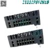
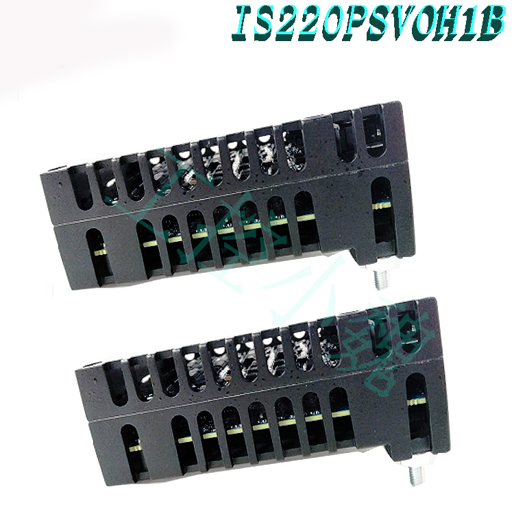
GE IS220PDIAH1A 336A4940CSP1 Discrete Input Module – Mark VI IS200
GE IS220PDIAH1A 336A4940CSP1 Discrete Input Module – Mark VI IS200
GE IS220PDIAH1A 336A4940CSP1 Discrete Input Module – Mark VI IS200
GE IS220PDIAH1A 336A4940CSP1 Discrete Input Module – Mark VI IS200
GE IS220PDIAH1A 336A4940CSP1 Discrete Input Module – Mark VI IS200
GE IS220PDIAH1A 336A4940CSP1 Discrete Input Module – Mark VI IS200
These models are used in conjunction with PDIA and are approved for use in hazardous locations. When used in hazardous environments, specific certifications are required. The certification ULE207685 is applicable to non hazardous, Class I Zone 2 Group IIC, and Class I Division 2 Groups A, B, C, and D locations. Specific certification is required for use in the ATEX Zone 2 Group IIC location, UL DEMKO 12 ATEX 1114875X.
.jpg)
The IS220PDIAH1A 336A4940CSP1 package has location standards, two of which are UL 600790 Ed. 5 and UL 60079-15 Ed. 3 for Class IIC, Zone 2. This information can be found in the GEH-6725 Mark VI Control Equipment Hazloc manual, which is located under the manual tab above.
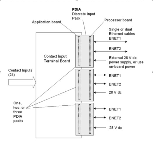
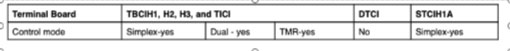
One I/O pack and one or two network connections are used in simplex.
Two I/O packs with one or two network connections are used by Dual.
Three I/O packs with one network connection each are used by TMR.
How to Install a PDIA Pack?
Mount the selected terminal board firmly.
Directly connect the PDIA I/O pack to the connections on the terminal board.
Use the threaded studs next to the Ethernet ports to mechanically secure the packs. The studs slip into a mounting bracket made for the particular style of the terminal board. It is important to position the bracket so that there is no right-angle force acting on the DC-37 pin connector between the terminal board and the pack. Only one adjustment should be necessary during the lifespan of the product.
Depending on the setup of the machine, connect either one or two Ethernet wires. Either port will allow the pack to function. When using dual connections, it is customary to link ENET1 to the network connected to the R controller.
.jpg)
If necessary, set up the I/O pack using the ToolboxST* program. See also the section on auto-reconfiguration.
OPERATIONS OF PDIA DISCRETE INPUT MODULE
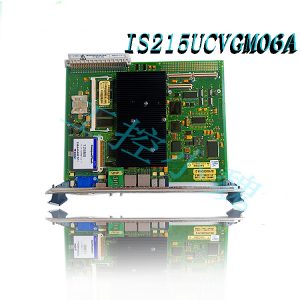
Each Mark VIe Ethernet I/O pack or module shares a processing board. It has the following in it:
A quick processor with RAM and flash memory is number one.
Two plugs for entirely independent 10/100 Ethernet ports
Hardware reset and watchdog timer circuit
A sensor for internal temperature
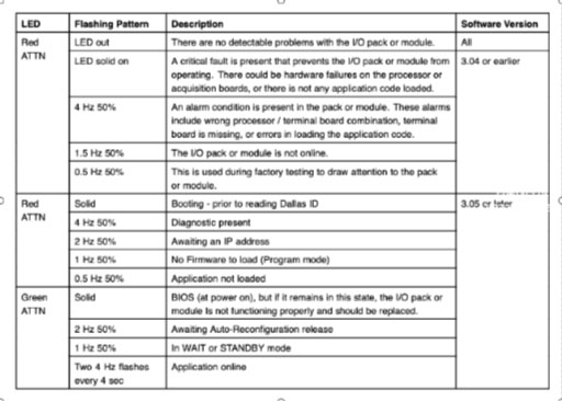
LEDs that indicate the status
The capacity to read IDs on other boards and electronic identification
An input power connector with a current limiter and a gentle start
Local power supplies, which also include monitoring and sequencing
The I/O pack or module function-specific acquisition board is connected to the processor board. The soft-start circuit ramps up the voltage available on the processor board when input power is applied. The processor reset is turned off and the local power supply is turned on in order. After finishing self-test routines, the processor loads application code from flash memory that is particular to the I/O pack or module type. To verify that the application code, acquisition board, and terminal board are correctly matched, the application code reads the board ID information. When there is a good match, the processor makes an effort to start Ethernet connections by asking for a network address.
The dynamic host configuration protocol (DHCP), which is the industry standard, and the terminal board’s unique identifier are both used in the address request. Following Ethernet startup, the CPU runs the application, programs the on-board logic, and permits the acquisition board to start working. The whole circuitry required to enable the I/O pack to function from one or two Ethernet inputs is contained in the processor application code. Both network pathways are constantly active when two Ethernet inputs are used. The I/O pack or module operation will not be hampered by a failure of either network, and the functioning network connection will reveal the failure. Compared to a traditional hot-backup system, where the second port is only used when the primary port fails to function, this configuration is more fault-tolerant. The processor’s Ethernet ports automatically negotiate between half-duplex and full-duplex operation at speeds between 10 MB/s and 100 MB/s.
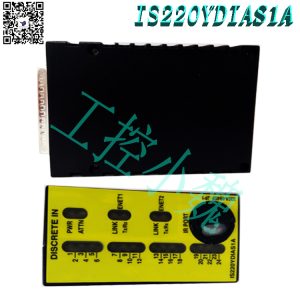
INPUT SIGNALS
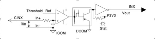
The second layer of signal conditioning and level shifting to connect the terminal board inputs to the control logic is provided by the discrete input acquisition board. On the terminal board, there is initial signal conditioning available. The comparator in the discrete input acquisition input circuit has a configurable threshold. A power supply isolated from the mains and an optocoupler isolate each input from the control logic. The inputs are connected to one another. The twenty-four inputs each have hysteresis, filtering, and a yellow status LED that flashes when an input is selected. When the input is lost, the LED will be off.(https://www.weikunfadacai1.com/)
VARIABLES THRESHOLDS IN DISCRETE INPUT MODULE
The contact wetting voltage input terminal serves as the source for the input threshold. This voltage is scaled in the majority of applications to offer an input threshold of 50%. To avoid an uncertain state in the case that the contact wetting voltage falls to zero, this threshold is clamped at 13 percent. The under-voltage detector notifies the control when the contact wetting voltage falls below 40% of the nominal voltage. There is a particular test mode available to force the control pack inputs. The threshold is pulsed high and low every four seconds to test the optocoupler’s responsiveness. Inputs that don’t reply are alarming.(https://www.weikunfadacai1.com/)
POWER MANAGEMENT IN I/O MODULE
Power management is a feature of the 28 V input circuit in the I/O pack. When applying power, the management function offers a gentle start to regulate the current inrush. A quick current limit function is provided by the circuit when power is applied to stop a pack or terminal board failure from spreading back into the 28 V power supply. The green PWR LED indicator will light up when there is power and everything is operating as it should. PWR LED will not light up again after the current limit function has been activated until the issue has been fixed.
CONNECTIONS
The discrete input terminal board is directly connected to the I/O pack by a DC-37 pin connector on the underside. The 24 input signals, ID signal, relay coil power, and feedback multiplex command are all included on the connector.
The main system interface is an RJ45 Ethernet connector labeled ENET1 on the side of the pack.
The redundant or secondary system interface is a second RJ45 Ethernet connector on the side of the pack with the name ENET2.
The pack and terminal board are powered by 28 V dc through a 3-pin power connector on the side of the pack.
FREQUENTLY ASKED QUESTION
What is IS220PDIAH1A 336A4940CSP1?
The IS220PDIAH1A 336A4940CSP1 is an I/O pack in the Mark VIe series.
Which software is commonly used for the Mark VIe control system?
ToolboxST is used as the common software platform for programming, configuring I/O, trending, and analyzing diagnostics for Mark VIe and related controls.
Comment on IS220PDIAH1A 336A4940CSP1
If discrete I/O packets are required, the PDIA model is most suitable for use in Mark VI systems. It must be used together with several related terminal boards to ensure its normal operation in hazardous areas. Please refer to the GEH-6725 manual for information on the required terminal boards- Xiongba Industrial Control
Model recommendation:
-300x300.jpg)
admin –
Compared to other models in the Mark VI series, the IS220PDIAH1A does not necessarily have a specific panel as it is an I/O pack. There are seven indicator lights on the front of the device, with three on the right side of the packaging as power indicator lights, two as link indicator lights