
-100x100.jpg)
-100x100.jpg)
Description
IS40yTBCIS3C- The simplex analog input terminal board is available in stock and will be shipped on the same day.
IS40yTBCIS3C- The simplex analog input terminal board is in an unused and rebuilt state.
If you want to get the best discount on IS40yTBCIS3C simplex analog input terminal board, please contact us and we will reply to you within 24 hours.
IS40yTBCIS3C Other names:
PCB board IS40yTBCIS3C
IS40yTBCIS3C interface board
Input/output module IS40yTBCIS3C
Product Description
IS40yTBCIS3C is a printed circuit board or PCB component in the Mark VI (MKVI) series of General Electric (GE). General Electric identifies this model as a Mark VI analog I/O pack terminal board. This model will be used in conjunction with the IS40yTBCIS3C Mark VI safety analog I/O package. This model is commonly referred to as a European style box type terminal block.
The IS40yTBCIS3C wiring board contains up to forty-eight (48) small silver terminals made of metal. Each terminal is labeled with its number in white font. The other end of IS40yTBCIS3C has a long connector port. This port is black and has many small female connectors installed on silver metal. Various electronic components are arranged vertically in the center of IS40yTBCIS3C. There are ten black potentiometers or variable resistors in these components. There is a semi-circular black small transistor next to each potentiometer. Four (4) additional potentiometer groups are located in the bottom right corner of IS40yTBCIS3C. Twenty (20) black jumpers are located between these jumpers. Each jumper is connected to a pair of silver metal jumper pins, thereby altering the functionality of the circuit board. Several small yellow capacitors are placed around the right half of IS40yTBCIS3C. These yellow capacitors have very small shapes, like small rectangles. Some integrated circuits can also be seen around IS40yTBCIS3C. These integrated circuits are very small and contain a tiny network of components.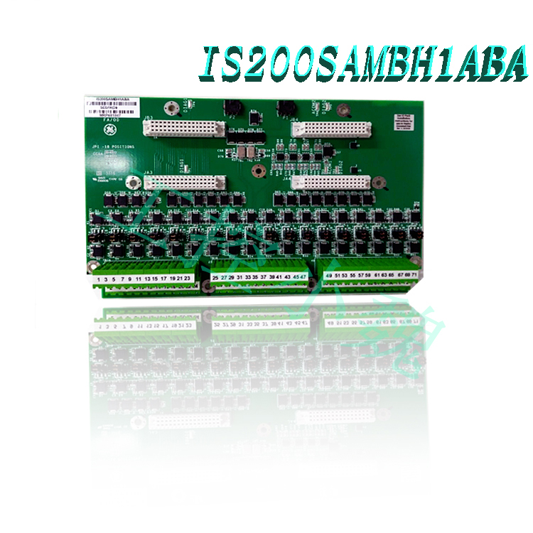
The IS40yTBCIS3Cmodel can be used for certification of multiple classified locations between hazardous and non hazardous locations. The non hazardous area marking of this model is UL E207685; Class I, Zone 2, Groups A, B, C, D, and Class I, Zone 2, and IIC have the same certification.
Function Description
IS40yTBCIS3Cis a simplex analog input terminal board developed by GE under the Mark VIe control system. The Simplex Analog Input (STAI) terminal board is a small analog input terminal board that can be connected to a battery pack and accept 10 analog inputs and two analog outputs. Ten analog inputs support two wire, three wire, four wire, and externally powered transmitters. Two analog outputs are 0-20 mA, but one can be jumper to 0-200 mA current. This board is only available in simplex configurations.
Features
High density European style terminal blocks: Using high-density European style terminal blocks, known for their excellent electrical and mechanical performance. These wiring terminals provide safe and reliable connections for various input and output signals, making system wiring easy and efficient.
On board ID chip for system diagnosis: In order to enhance system diagnosis and monitoring, this component is equipped with an onboard ID chip. This chip can uniquely identify the motherboard to the system for easy identification and troubleshooting. It provides important information about the status and configuration of the motherboard, making maintenance and troubleshooting processes more simplified and effective.
Compatibility with PAIC I/O packages: Fully compatible with PAIC I/O packages. This compatibility ensures seamless integration between STAI and PAIC I/O packages, enabling smooth and synchronized exchange of data and signals.
Ethernet connection: I/O packets are connected to the controller via Ethernet, enabling fast and reliable communication between the I/O packets and the central controller. Ethernet has become a widely used communication protocol in industrial applications due to its high data transfer rate, low latency, and robustness.
D-type connector: This kit is equipped with a D-type connector, which can be easily and safely connected to the controller. D-type connectors are a standard interface widely used in industrial applications due to their reliability and ease of use..jpg)
Support for simplex systems: Designed specifically to support simplex systems. In a simplex configuration, a single controller and I/O package work together to ensure system operation. This setting simplifies the system architecture and is typically used in applications where redundancy is not a critical requirement.
Supports long cable length: allows a maximum bidirectional cable resistance of 15 ohms and supports cable lengths up to 300 meters. This feature is very useful in installations where I/O packages need to be installed far away from the controller, without affecting signal integrity and performance.
Installation
During the installation of STAI (signal transmitter analog input), there are several steps and precautions to consider.
This module is installed together with plastic insulators on a metal plate bracket. This bracket provides a stable platform for the module and ensures correct alignment. The bracket can be further installed on DIN rails, providing a standardized method for installation in industrial environments. Alternatively, STAI modules with insulators can be directly installed on metal plate components and securely fixed to cabinets or other suitable surfaces with bolts.
For wiring, it is recommended to use 18 AWG wires, preferably shielded twisted pair. These cables are designed to minimize electromagnetic interference and ensure reliable signal transmission. Using shielded twisted pair cables helps maintain the integrity of analog signals and reduces the risk of noise or signal attenuation.
This component includes wiring terminals for easy connection of analog inputs and outputs. These wiring terminals can serve as interface points for various analog signals supported by the module. The supported analog input types include two wire transmitters, three wire transmitters, four wire transmitters, externally powered transmitters, and voltage inputs with a range of ± 5 V or ± 10 V DC. Similarly, the module supports analog output signals in the current range of 0-20 mA and 0-200 mA.
To ensure proper grounding and minimize interference, I/O cable shielding terminals are provided. This terminal allows for the connection of shielded cables, which helps to protect analog signals from external electrical noise and interference.
By following appropriate installation procedures and utilizing proper wiring and connections, the STAI module can be successfully integrated into the system, achieving reliable analog signal transmission and processing.
Surgery
Power supply: All transmitters connected to the terminal board can use a 24V DC power supply. This power supply ensures stable and reliable power supply for sensors or transducers used in the system.
Input selection: By using jumpers, you can choose between the current and voltage inputs of the STAI module. This flexibility is compatible with various sensors that provide current or voltage output, depending on the specific requirements of your application.
Analog output circuit: The STAI module is equipped with two analog output circuits. A circuit operates within the range of 4-20 mA current and provides a standardized output signal. The second circuit can be configured to operate within a range of 4-20 mA current or a wider range of 0-200 mA through jumpers. The selection of output range depends on the compatibility requirements of the specific application and receiving device or system.
Limitations of TMR or TBAI applications: It should be noted that the terminal board of the STAI module cannot be used for Triple Module Redundancy (TMR) or Terminal Board Analog Input (TBAI) applications. This limitation stems from the fact that there is only one cable connection on the terminal board, which is not sufficient to achieve the redundant or extended input functions typically required in TMR or TBAI settings..jpg)
Configuration
It provides configuration options by using jumpers. These jumpers play a crucial role in customizing the functionality of the circuit board according to specific requirements. By referring to the installation diagram, the positions of these jumpers can be identified.
Jumpers J1A to J8A provide the function of selecting the current or voltage input of the terminal board. This flexibility is compatible with different types of input signals and meets the needs of various applications.
Jumpers J1B to J8B determine whether the circuit is connected to the common terminal. The common terminal is used as a reference point or ground for input signals. By adjusting these jumpers, it can be determined whether each input circuit is connected to the common terminal.
To accurately select the input current, jumpers J9A and J10A can be used. These jumpers allow you to choose an input current of 1 mA or 20 mA based on the specific requirements of the system.
In addition, jumpers J9B and J10B can also affect the connection back to the common terminal, further controlling the circuit configuration.
Among the available jumpers, J0 has a unique purpose. Jumper J0 allows for the selection of 20 mA or 200 mA for output 1, providing the necessary flexibility to adapt the output of the terminal board to the required specifications.
Diagnosis
The board integrates diagnostic tests on the terminal board to ensure proper functionality and identify potential issues. These diagnostic tests involve specific mechanisms and devices that enable the board to detect and report faults or hardware incompatibilities. The diagnostic procedure is as follows:
Voltage drop test: The circuit board uses a series resistor to measure the voltage drop at both ends, thereby indicating the output current. By monitoring voltage drop, the I/O processor of the circuit board can evaluate the health status of the output. If either of the two outputs deviates from the expected value or becomes unhealthy, the I/O processor will generate diagnostic alerts or faults. This fault alert will notify users or system administrators that there may be a problem output, enabling them to take appropriate measures to correct the problem.
Cable connector ID device: Each cable connector on the terminal board is equipped with its own ID device. This ID device is an integrated chip that contains basic information, including the serial number of the terminal board, board type, revision number, and connector location (JR, JS, JT). The ID device is a read-only chip, which means it can be queried by the board’s I/O controller to retrieve encoded information.
During the diagnostic process, the I/O controller reads information from the ID device of each cable connector. It compares this information with expected values, which are usually pre programmed or stored in the system. If a mismatch or inconsistency is detected between the read data and the expected value, it indicates a hardware incompatibility between the terminal board and the connected cable. In this case, the I/O controller will generate a hardware incompatibility fault, indicating a mismatch between the terminal board and the connected cables.
Hardware incompatibility faults can alert users or technicians that the current wiring board configuration and connected cables may be incompatible. In this way, they can solve the problem by ensuring the correct cables are used or making necessary adjustments to achieve compatibility.
By integrating these diagnostic tests, it provides a mechanism for detecting potential faults and hardware incompatibilities. These diagnostic programs enable the circuit board to monitor and evaluate the health status of its output, and verify the compatibility between the terminal board and the connecting cables. The generated diagnostic alerts and hardware incompatibility faults can serve as valuable information for troubleshooting and maintenance, helping to quickly identify and resolve any potential issues encountered during circuit board operation.
Frequently asked questions
What is IS40yTBCIS3C?
This is a simplex analog input terminal board developed by GE
What types of analog inputs do STAI support?
It supports a range of transmitters, including two wire, three wire, four wire, and externally powered transmitters.
What are the specifications for analog output?
Two analog outputs are 0-20 mA, but one can be jumper to 0-200 mA current.
What type of terminal blocks are used?
It uses high-density European style terminal blocks.
What is the maximum supported cable length?
STAI supports cable lengths up to 300 meters, with a maximum lead resistance of 15 ohms and a maximum bidirectional cable resistance of 15 ohms.
What is the purpose of onboard ID chips?
The onboard ID chip can recognize the circuit board and battery pack, thereby achieving system diagnosis.
What model does the IS40yTBCIS3Cunit belong to?
The IS40yTBCIS3Cmodel is one of the Mark VI analog I/O pack terminal boards. When operating, the IS200STAIS2A model is usually used in conjunction with the Mark VIeS secure analog I/O package. The I/O package is marked as IS220YAICS1A. In addition to the IS220YAIC model, the IS40yTBCIS3C unit can also be used in conjunction with IS2000STAIS1A, IS400STAIS1A, IS400STAIS2A, IS 200TBAIS1C, and IS400TBAIS1C. For information on how these models work together, please refer to the GEH-6725 user manual.
What are the equipment markings for STAIS models in Class I, Zone 2, USA and Canada?
The IS40yTBCIS3Cmodel in Class I, Zone 2 of the United States and Canada is marked as Class I, Zone 2, AEx nA nC [nC] IIC T4, Ex nA nL [nL] IIC T4 Gc X. Other device markings can also be used on the IS200STAIS2A model. For these markings, please refer to page 137 of the GEH-6725 user manual.
Comment on IS40yTBCIS3C
One drawback of the IS40yTBCIS3C model is limited information. It is known that the model is used in conjunction with a security simulation I/O package, but it is unknown how it works and what it does when used in conjunction with a YAIC package. For more information on the functionality of this model, please refer to the General Electric documentation.
All products on this website are special products, and market prices have been fluctuating,
The specific customer service quotation shall prevail, as the product is a new product and the price is not genuine,
Please confirm the model, product, price, and other detailed information with customer service before placing an order. The website has been used,
The new one is for sale, please contact customer service to communicate.
Discounted product recommendations:
IS200STAIS1A
IS220YAICS1A
IS200WNPSH1A
IS200TVBAH2A
IS220PVIBH1A
IS220PTURH1B
IS220PTURH1A
IS200TRPAH1A
IS220PTCCH1B
IS200STTCH2A
IS200AEPAH1BKE
IS215WEPAH2B
IS420YAICS1B
More……
-300x300.jpg)
-300x300.jpg)
Reviews
There are no reviews yet.