Description
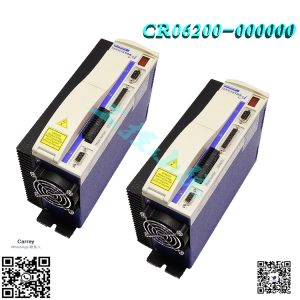
For system startup you need a PC with MOTIONLINK for windows, LE- CD-LITE drive brush less motor, and your application connected to the motor. With MOTIONLINK, you can initialize and configure you drive to your application. After that, you will connect the drive to your servo controller. You can communicate with the SERVOSTAR CD-Lite through the serial port. Since MOTIONLINK is designed to guide you through the operation process of the drive, the MOTIONLINK discussion in this section covers only general steps of use. A “dumb terminal” can also be used to communicate to the drive. You may find this method of communication very awkward until a certain level of familiarity with the drive’s operation is achieved. MOTIONLINK also provides a terminal emulation feature that contains many useful editing tools for this type of communication. Computer Requirements MOTIONLINK requires an IBM-PC or compatible computer with the following features: ♦ IBM-compatible, Pentium or higher computer. ♦ 16 M RAM. ♦ Windows 95, Windows98, WindowsNT 4.0 with Service Pack 3, Windows 2000. ♦ CD-ROM player. ♦ Standard Video Adapter (CGA, MDA, EGA, MCGA, VGA, or SVGA). ♦ Serial Port (for communication link with SERVOSTAR CD-Lite). The serial communications port may be COM1, COM2, COM3, or COM4. COM1 is the normal configuration: COM1: Address 3F8h, Interrupt Request #4 COM2: Address 2F8h, Interrupt Request #3 COM3: Address 3E8h, Interrupt Request #4 COM4: Address 2E8h, Interrupt Request #3
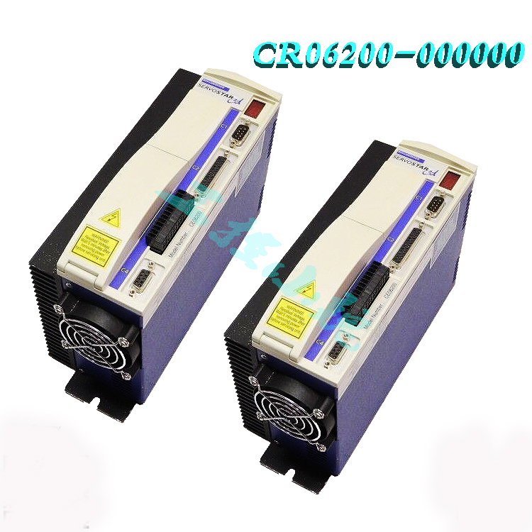
Installing MOTIONLINK ♦ Insert the CD-ROM to load MOTIONLINK for Windows. ♦ The CD-ROM should AUTORUN. If not, select Start | Run (or browse your CD-ROM drive). ♦ Type “D:AUTORUN.EXE” and press the Enter key (this assumes your CD player has a D: letter designation). ♦ Select a product and follow the instructions on the screen. To run the program, go to your Start/Programs listing and select SERVOSTAR MOTIONLINK from the menu (or click on the SERVOSTAR MOTIONLINK icon if loaded on the desktop). Using MOTIONLINK MOTIONLINK gives you three methods to configure the drive. The first uses a Startup Wizard and is the easiest and most highly recommended approach. Its main purpose is for initial startups. The second approach allows you to more indirectly perform the same configuration as the first using the Main MOTIONLINK screen. This method is most convenient when corrections to an existing configuration are required. The third method uses the Terminal Mode screen to directly set (or monitor) values for the same variables and commands that the other two methods configure through a more friendly user interface. You can gain a more thorough understanding of the SERVOSTAR drive, MOTIONLINK, and its variable and command set by using the context-sensitive Help (F1) provided in MOTIONLINK. When you begin, the first screen you see is: Startup Wizard This screen appears the first time (and any time after should you choice not to deselect it) MOTIONLINK is run on a PC. It is designed to guide you through a step-by-step approach to configure a drive. Click the “START” button on the first user screen and walk through the complete sequence of buttons provided to set the drive, motor, and application (Opmode, Tune, Backup, Go) variableparameters.
Feedback The SERVOSTAR provides a motor position output to you in the form of quadrature encoder signals eliminating the need for an additional position feedback device. The outputs are differential line drivers. There is an associated DC common output (C4: pin 3) which can connect to your port to keep common mode noise and voltage spikes minimized for device protection. Because there are normally differences of potential between your controller and the drive, connection is recommended (if ground loops occur, disconnect and retest). The source of the Encoder Equivalent Output (EEO) signals depends on the type of motor feedback device: This section describes the various feedback types and how they function beginning with firmware version 0.1.8.
Incremental Encoder The output signal is the actual encoder feedback signal that is pre-configured (MENCRES) in the drive’s motor parameters. It can be scaled down by multiples of two (ENCOUTO: 1, 2, 4, 8, 16) and has a maximum frequency limit of 3 MHz. The SERVOSTAR can use encoder feedback to monitor the motor shaft position. As opposed to a resolver, which is an absolute position feedback device, the encoder is an incremental device that indicates changes in position. The encoder resolution of the SERVOSTAR (and therefore the drive’s encoder equivalent output) is fixed because it is a hardware characteristic of the encoder device. The encoder interface includes three groups of wires: 1. A/B (and complements) lines make up the encoder quadrature signals. The signals are received differentially through line receivers before being passed through a wire-break detection circuit. 2. The narrow Index pulse normally appears once per revolution and indicates a known physical position of the shaft. This pulse is received differentially through a line receiver before being passed through a wire-break detection circuit. This signal is hardwarecapturable. 3. Hall signals provide information representing the approximate absolute location of the motor shaft. From this information, the motor can sinusoidally commutate forward until the index signal is detected – at which time, true position is known. These signals are isolated by an opto-coupler and can be differential or open-collector type signals.
Cable Lengths The recommended cable length when using the SERVOSTAR to source the encoder is no longer than 50 ft. (15 m). Long encoder cables tend to have high DC resistance that may create significant loading effects in the supply lines to the encoder. Please consider this carefully when designing the system. An option that would allow the use of longer lengths, implements a separate supply located at the motor to source the encoder. Quadrature signals returned to the drive are differentially connected which normally do not constitute a problem with longer cable lengths. Resolution and Accuracy A SERVOSTAR encoder-based system typically exhibits minimal inaccuracies outside of the encoder itself. To get an approximate total value the customer need only look to the specifications listed for the encoder being used.
Resolver The SERVOSTAR uses either single (two poles) or multi-speed (multiple poles) resolver feedback to monitor the motor shaft position. A resolver can be thought of as a transformer whose output is unique for any given shaft position (an absolute position feedback). The transformer is driven with a sinewave reference signal. Two AC signals are returned from the resolver into the Sine and Cosine inputs. All three of these sinewave signals are low-level and susceptible to noise.
-2.jpg)
Cable Lengths It is important to use properly- shielded cable and to keep it away from other noise-radiating devices and cables. It is not recommended to run the feedback and motor cables in the same conduit. Danaher Motion Kollmorgen has tested cable lengths up to 75 ft. (22.9 m). without degradation of performance. However, performance may vary, depending on motor and resolver type. Tests were performed with standard Danaher Motion Kollmorgen cable and its lowimpedance and Danaher Motion Kollmorgen GOLDLINE motor resolver. Please consult the factory for cable and resolver impedance specifications when long cable runs above 250 ft. (76 m) are desired. Danaher Motion Kollmorgen recommends twisted-shielded pair for feedback cables.
Resolver Systems The output signal is developed through the R/D hardware circuitry for minimal phase lag and has a maximum frequency determined by the motor speed and R/D limits. It provides a configurable (ENCOUT) resolution of up to 16384 lines (65536 quad counts) per revolution of the motor shaft. The placement of the index pulse (INDEXPOS) can be varied on resolver systems within 360 electrical degrees of the feedback signal. For single-speed resolvers, this means you can vary the position of this signal over one mechanical revolution. For multi-speed resolvers, the mechanical position variation is determined by the pole-pair count of the resolver (e.g. threespeed resolver gives mechanical variation of the pulse within 1/3 of a revolution). Encoder Systems The output signal is the actual encoder feedback signal that is pre-configured (MENCRES) in the drive’s motor parameters. It can be scaled down by multiples of two (ENCOUTO: 1, 2, 4, 8, 16) and has a maximum frequency limit of 3 MHz.
Operational Modes The SERVOSTAR CD-Lite has the ability to assume different modes of operation. It is factory configured in OPMODE=1 (Analog Velocity Controller) but may be reconfigured by the user. Not all commands and variables are active or meaningful in every OPMODE. OPMODE = 1 Analog Velocity Controller. The SERVOSTAR CD-Lite is configured as a velocity-loop controller and is controlled via a ± 10V analog input signal. The commanded velocity is proportional to the input voltage. OPMODE = 3 Analog Torque (Current) Controller. The SERVOSTAR CD-Lite is configured as a torque-loop controller and is controlled via a ± 10 V analog input signal. The commanded current is proportional to the input voltage. System I/O This section discussions the I/O features of the C3 connector (except for the Thermostat input on C2 see appendix). Electrical specifications are in the Quick Start Guide. Analog Input (ANIN1) The velocity or torque loop can receive its command from an analog voltage source and is selectable through the OPMODE variable. The analog input to the SERVOSTAR CD-Lite is differential. This means that the signals received at the two inputs are subtracted from each other to create a ‘difference,’ that is used to command the rest of the system. This type of input has a high degree of noise immunity and, in many cases, will allow for ground isolation between systems. This analog input also has a low pass filter (ANLPFHZ) to prevent high frequency noise from entering the system. The input voltage from the differential receiver is applied to a precise 12-bit Analog-to-Digital (A/D) conversion system. The A/D conversion system is read by the microprocessor, 250µs for the velocity loop mode, and every 62.5µs for the torque (current) loop mode of operation. Encoder-based units have the additional benefit of a Dual Gain (ANDG) input. When enabled, the system uses two 14-bit A/D inputs to read the user-supplied analog signal. One input is a direct reading of the ± 10V signal, while the other incorporates a 2x gain term. When the input voltage is less than 4V, the 2x channel is used to determine the user’s input voltage. This extends the resolution to a 15-bit equivalent. Above 4V, the system uses the straight 14-bit conversion. Special software algorithms are used to minimize cross-over distortion and add 0.25 V hysterisis. Analog systems often require scaling and offset bias. The SERVOSTAR CD-Lite adds an analog offset (ANOFF1) variable to this reading, performs an analog deadband (ANDB) adjustment, and scales it through velocity loop input scaling (VSCALE), or torque loop input scaling (ISCALE) before passing the data to the selected control loop. The analog input (ANIN1) variable indicates the analog reading after the offset (ANOFF1) and the deadband (ANDB) adjustments, but before the loop scaling. The ANIN1 variable range is ± 22500 counts (or mV). The SERVOSTAR CD-Lite also has an automatic analog input zeroing function. Invoking the ANZERO command while the drive is enabled or disabled samples motor velocity over a 32 ms period and updates ANOFF1 accordingly to cancel out analog input offset. This command uses an internal offset mechanism that has finer resolution than ANOFF1 is capable of providing.
Remote Enable Input (REMOTE) The opto-isolated Remote Enable input (REMOTE) provides a hardware drive enable switch. This 12-24 VDC input disables or enables the power stage output to the motor. The signal must be customersupplied to get the drive to enable (in combination with other parameters; ACTIVE) and operate. Tapping the signal off the logic supply (C5) is not recommended. The toggling of this switch also initiates an attempt to recover from a fault condition. Fault Output Relay (RELAY, RELAYMODE) The SERVOSTAR CD-Lite provides a drive ready/drive up output in the form of a relay (RELAY) output. The relay (RELAY) output is controlled by the SERVOSTAR CD-Lite’s microprocessor. There is a software switch (RELAYMODE) that configures the relay (RELAY) output to act as a ‘Drive Ready’ or ‘Drive Up’ indicator: If RELAYMODE = 0, the relay is closed when the drive is error free and ready to run. This is a ‘Drive Ready’ configuration. If RELAYMODE = 1, the relay is closed only when the drive is enabled. This is a ‘Drive Up’ configuration (ACTIVE equals 1). If RELAYMODE = 2 is not avalible with CD-LITE. If RELAYMODE = 3, the relay is open when no faults are latch and closed when the drive detects a fault. Limit switches The SERVOSTAR CD-Lite provides two limit switches only in Velocity mode, one for CW direction of the shaft and one for CCW direction of the shaft. To enable limit switch mode LIMIDIS should be zero. Operational mode for both sides
Torque Loop Most applications use the SERVOSTAR CD-Lite in torque mode configuration. The SERVOSTAR CDLite has many internal variables that can be used to examine and dictate system operation. Many of these variables and their locations in MOTIONLINK are presented graphically in the following discussions to help disclose meanings and relationships. Analog Torque The SERVOSTAR CD-Lite is most often configured to operate as an analog torque loop controller (OPMODE=3). In this case, the current loop receives its input from the analog-to-digital (A/D) conversion system. After conversion, the input command signal is processed through an algorithm that adjusts the signal (ANOFF1, ANDB, ANZERO), filters it (ANLPFHZ) and scales it (ISCALE), before developing the current command. The current (or torque) command is checked against the peak (IMAX, ILIM) and continuous (FoldBack features, ICONT) current clamp limits. Sinusoidal commutation modulation is added to the command and fed to the three-phase current loop regulator, which calculates a current error. This error is fed through a digital pole-placement compensation algorithm. The output of the compensator is converted to a PWM signal and fed to the power transistor bridge. The power bridge uses the high voltage DC BUS Module (325 VDC bus typical) to supply the required current to the motor windings. The actual motor current is updated and the process begins again. Current Sampling The current loop receives corrective feedback from the current sampling circuitry. The current sensors use closed-loop hall sampling techniques in all units. The current sample is used by the current loops to regulate the current in each of the three motor phases. Two phases (A and C) of the current signal are sampled by the microprocessor at a 16 kHz rate. The momentary A phase current and C phase current are monitored by examining the IA and IC variables, respectively. The microprocessor calculates the equivalent absolute current, which can be monitored as I. This value can be averaged for 2, 4, 8, 16, 32, or 64 samples.
Model recommendation:


-2-100x100.jpg)
Reviews
There are no reviews yet.