Description
Many products have not been listed yet. For more products, please contact us
If the product model is inconsistent with the displayed image, the model shall prevail. Please contact us for specific product images, and we will arrange for photos to be taken and confirmed in the warehouse
We have 16 shared warehouses worldwide, so sometimes it may take several hours to accurately return to you. We apologize for any inconvenience caused. Of course, we will respond to your concerns as soon as possible
MVME188A Other names:
Processor moduleMVME188A
MVME188A Intelligent embedded computer
Dual height VME moduleMVME188A
MVME188A Control board
Cooling Requirements
The Motorola MVME162 Embedded Controller is specified, designed, and tested to operate reliably with an incoming air temperature range from 0° to 55° C (32° to 131° F) with forced air cooling at a velocity typically achievable by using a 100 CFM axial fan. Temperature qualification is performed in a standard Motorola VMEsystem 3000 chassis. Twenty-five watt load boards are inserted in two card slots, one on each side, adjacent to the board under test, to simulate a high power density system configuration. An assembly of three axial fans, rated at 100 CFM per fan, is placed directly under the VME card cage. The incoming air temperature is measured between the fan assembly and the card cage, where the incoming airstream first encounters the controller under test. Test software is executed as the controller is subjected to ambient temperature variations. Case temperatures of critical, high power density integrated circuits are monitored to ensure component vendors specifications are not exceeded.
While the exact amount of airflow required for cooling depends on the ambient air temperature and the type, number, and location of boards and other heat sources, adequate cooling can usually be achieved with 10 CFM and 490 LFM flowing over the controller. Less airflow is required to cool the controller in environments having lower maximum ambients. Under more favorable thermal conditions, it may be possible to operate the controller reliably at higher than 55° C with increased airflow. It is important to note that there are several factors, in addition to the rated CFM of the air mover, which determine the actual volume and speed of air flowing over the controller
Special Considerations for Elevated Temperature Operation
The following information is for users whose applications for the MVME162 may subject it to high temperatures.
The MVME162 uses commercial grade devices. Therefore, it can operate in an environment with ambient air temperatures from 0° C to 70° C. Several factors influence the ambient temperature seen by components on the MVME162. Among them are inlet air temperature; air flow characteristics; number, types, and locations of IndustryPack (IP) modules; power dissipation of adjacent boards in the system, etc
A temperature profile of the MVME162-023 was developed in an MVME945 12-slot VME chassis. This board was loaded with one GreenSpring IP-Dual P/T module (position a) and three GreenSpring IP-488 modules (positions b, c, and d). One twenty-five-watt load board was installed adjacent to each side of the board under test. The exit air velocity was approximately 200 LFM
between the MVME162 and the IP-Dual P/T module. Under these conditions, a 10° C rise between the inlet and exit air was observed. At 70° C exit air temperature (60° C inlet air), the junction temperatures of devices on the MVME162 were calculated (from the measured case temperatures) and did not exceed 100° C.
FCC Compliance
The MVME162 was tested without IndustryPacks in an FCC-compliant chassis and meets the requirements for Class A equipment. FCC compliance was achieved under the following conditions:
Shielded cables on all external I/O ports
Cable shields connected to earth ground via metal shell connectors bonded to a conductive module front panel.
Conductive chassis rails connected to earth ground. This provides the path for connecting shields to earth ground.
Front panel screws properly tightened.
For minimum RF emissions, it is essential that the conditions above be implemented. Failure to do so could
Intelligent embedded computer
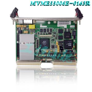
The MVME162 is a double-high VMEmodule equipped with an MC68LC040 or optional MC68040 microprocessor. (The MC68040 microprocessor has a floating-point coprocessor; the MC68LC040 does not.)
The MVME162 has 1MB, 4MB, or 8MB of parity-protected DRAM; 512KB SRAM (with battery backup); a TOD clock (with battery backup); an optional LAN Ethernet transceiver interface with DMA, two serial ports (EIA-232-D and EIA-232-D/EIA-530); six tick timers with watchdog timer(s); optional SCSI bus interface with DMA; VMEbus interface (local bus to VMEbus/VMEbus to local bus, with A16/A24/A32, D8/D16/D32 bus widths and a VMEbus system controller).
Input/Output
Input/Output (I/O) signals are routed through backplane connector P2. A P2 adapter board or LCP2 adapter board routes the signals and grounds from connector P2 to an MVME712 series transition module (MVME712-12, MVME712-13, MVME712A, MVME712AM, or MVME712M). The transition module routes the signals to the appropriate configuration headers and industry-standard connectors. Refer to the MVME712-12, MVME712-13, MVME712A, MVME712AM, and MVME712B Transition Modules and LCP2 Adapter Board User’s Manual or the MVME712M Transition Module and P2 Adapter Board User’s Manual for more information
All products on this website are special products, and market prices have been fluctuating,
The specific customer service quotation shall prevail, as the product is a new product and the price is not genuine,
Please confirm the model, product, price, and other detailed information with customer service before placing an order. The website has been used,
The new one is for sale, please contact customer service to communicate.


.jpg)


-100x100.jpg)


admin –
The Motorola MVME162 Embedded Controller is specified, designed, and tested to operate reliably with an incoming air temperature range from 0° to 55° C (32° to 131° F) with forced air cooling at a velocity typically achievable by using a 100 CFM axial fan. Temperature qualification is performed in a standard Motorola VMEsystem 3000 chassis. Twenty-five watt load boards are inserted in two card slots, one on each side, adjacent to the board under test, to simulate a high power density system configuration. An assembly of three axial fans, rated at 100 CFM per fan, is placed directly under the VME card cage. The incoming air temperature is measured between the fan assembly and the card cage, where the incoming airstream first encounters the controller under test. Test software is executed as the controller is subjected to ambient temperature variations. Case temperatures of critical, high power density integrated circuits are monitored to ensure component vendors specifications are not exceeded.
admin –
While the exact amount of airflow required for cooling depends on the ambient air temperature and the type, number, and location of boards and other heat sources, adequate cooling can usually be achieved with 10 CFM and 490 LFM flowing over the controller. Less airflow is required to cool the controller in environments having lower maximum ambients. Under more favorable thermal conditions, it may be possible to operate the controller reliably at higher than 55° C with increased airflow. It is important to note that there are several factors, in addition to the rated CFM of the air mover, which determine the actual volume and speed of air flowing over the controller