

.jpg "VT3024(1)")


-100x100.jpg)
Description
Describe
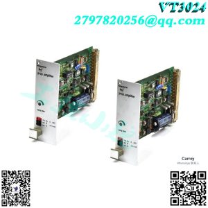
Score 4, with 8 comments on Rexroth, Indramat, and Bosch’s VT-VSPA1-1-11 in the VT-VSPA1 series. The VT-VSPA1 proportional valve amplifier controls the solenoid current of the Rexroth proportional valve, without the need for LVDT position feedback. This VT-VSPA1-1-11 provides 11 component families, factory assigned additional features, and+24 VDC+40% -5% operating voltage. Other functions include a 32 pole male multipoint connector and connection type front panel, as well as operation control of pressure valves. Before debugging the amplifier, it is necessary to ensure that the DIL switch on the printed circuit board has been set according to the relevant application before project planning/maintenance instructions/additional information. Under the provided conditions, the parameter settings are as follows (refer to pages 8-10 for parameter settings): maximum ramp time=5 seconds, pilot current=100 mA, maximum output current=800 mA, and clock frequency=200 Hz. The amplifier board can only be assembled during power outage. Do not use connectors with freewheeling diodes or LED displays for the connection of the upper solenoid valve. Only instrument R:>100 kQ can be used for measurement on the board. Compared to the 0V working voltage, the measurement zero point (MO) has increased by+9 V and there is no isolation, i.e. -9 V has been adjusted for the voltage ▲ 0 V working voltage. Therefore, do not connect the measurement zero point (MO) to the 0V working voltage. For switching command values, relays with gold-plated contacts (low voltage, low current) must be used. Always shield the command value line, connect the shield to the grounding on the card side, and open the other side. The card must be connected to ground through terminal 6 or 8. If there is no system ground, connect a 0 V working voltage. Bu Suggestion: Also, shield the electromagnetic coil wire. For solenoid conductors with a length not exceeding 50 meters, use a 1.5 mm2 linear LiYCY. For more information, please contact us. The distance from overhead lines, radio, and radar systems must be at least 1 meter. Do not place the solenoid coil wire and signal wire near the power cord. The charging power of the smooth capacitor on board 1 requires the pre fuse to have a slow melting characteristic. Note: If using differential input, both inputs must always be connected or disconnected simultaneously. Troubleshooting If the amplifier card does not work, please perform the following steps. Note: Troubleshooting is required: The output stage is turned off when the temperature is too high. 1. Is the working voltage available? (e.g. due to overload). This error is caused by the “H2” LED indicating contacts 24 (ac) and 18 (ac) being turned off. Is the fuse on the card faulty? If the cable for input “4 to 20 mA” is disconnected, is the “Ready 3. Is there an internal+9 V working voltage on the card? Operation” signal reset and the “H2” LED will go out? 4. If an internal command value potentiometer is used, is the bridge from 10 (AC) to 12 (AC) also available? The following applies to component series 11:5. Is the external potentiometer correctly connected? If the solenoid valve is short circuited or the cable is broken -6. Is the differential input connected correctly? Conduit, prepare for operation output to control timing: reference potential to 30 (ac) “H2” LED will flash as soon as possible at a frequency of 0.5 to 2 Hz from 0 to+10 V to 28 (ac) because the command value is greater than 2% at the same time. 7. Is the solenoid valve connected correctly? If the card is removed, the resistance must be approximately 20 Q to 300 or 50 to 8 Q at contacts 22ac and 20ac depending on the valve type. The modification of the connection name in parentheses only applies to VT-VSPA1-1 type. Feature: Differential input of voltage and current with individually adjustable ramp time “up/down” ramp generator External ramp time preset enable input working voltage reverse protection Short circuit protection and wire break detection of electromagnetic conductor Clock power output stage “Ready for operation” message
More recommendations:
Reviews
There are no reviews yet.