Description
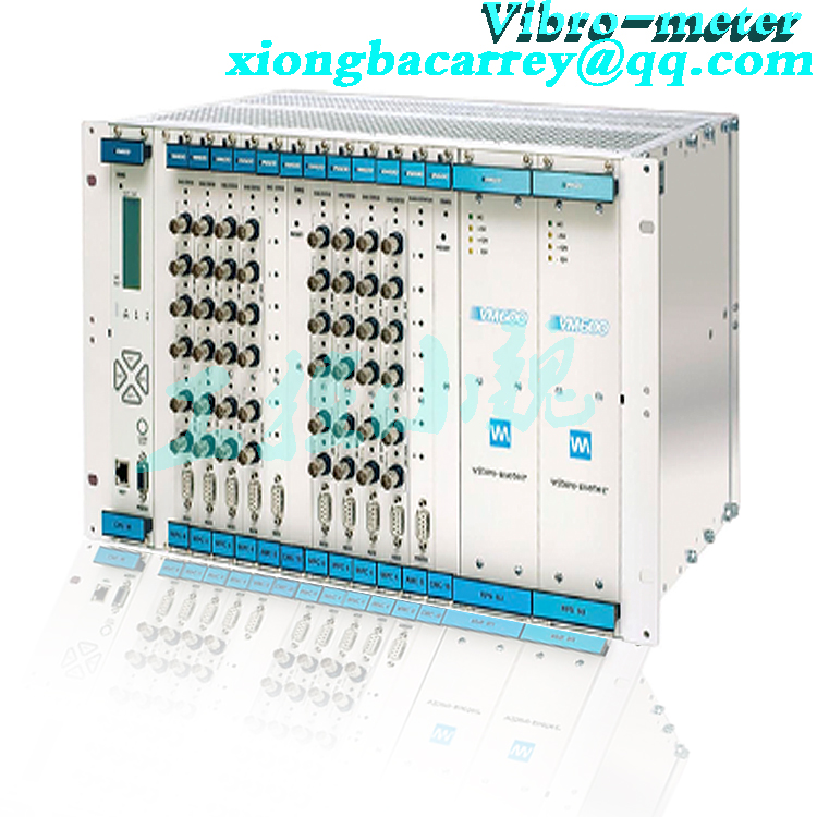
DESCRIPTION Introduction The VM600 CPUM and IOCN modular CPU card and input/output card is a rack controller and communications interface card pair that acts as a system controller and data communications gateway for a VM600 rack-based machinery protection system (MPS) and/or condition monitoring system (CMS) from Meggitt’s Vibro-Meter® product line. Different versions of CPUx/IOCx card pair Different versions of CPUx/IOCx rack controller and communications interface card pair are available, as follows: •

.jpg)
CPUM/IOCN card pair and VM600 racks The CPUM/IOCN card pair is used with a VM600 ABE04x system rack and a CPUM card can be used either alone or with an associated IOCN card as a card pair, depending on the application/system requirements. The CPUM is a double-width card that occupies two VM600 rack slots (card positions) and the IOCN is a single-width card that occupies a single VM600 slot. The CPUM is installed in the front of the rack (slots 0 and 1) and an associated IOCN is installed in the rear of the rack in the slot directly behind the CPUM (slot 0). Each card connects directly to the rack’s backplane using two connectors. Note: The CPUM/IOCN card pair is compatible with all VM600 ABE04x system racks. CPUM rack controller and communications interface functionality The modular, highly versatile design of the CPUM means that all VM600 rack configuration, display and communications interfacing can be performed from a single card in a “networked” rack. The CPUM card acts as a “rack controller” and allows an Ethernet link to be established between the rack and a computer running one of the VM600 MPSx software packages (MPS1 or MPS2). The CPUM front panel features an LCD display that shows information for the CPUM itself and for protection cards in a VM600 rack. The SLOT and OUT (output) keys on the CPUM front panel are used to select which signal to display. As a fieldbus communications interface for a VM600 monitoring system, the CPUM communicates with MPC4 and AMC8 cards via the VME bus and with XMx16/XIO16T card pairs via an Ethernet link in order to obtain measurement data and then share this information with third-party systems such as a DCS or PLC. LEDs on the CPUM front panel indicate the OK, Alert (A) and Danger (D) status for the currently selected signal. When Slot 0 is selected, the LEDs indicate the overall status of the whole rack. When the DIAG (diagnostic) LED shows green continuously, the CPUM card is operating normally, and when the DIAG LED blinks, the CPUM card is operating normally but access to the CPUM card is restricted due to VM600 MPS rack (CPUM) security. The ALARM RESET button on the front panel of the CPUM card can be used to clear the alarms latched by all protection cards (MPC4 and AMC8) in the rack. This is a rack-wide equivalent of resetting alarms individually for each card using discrete signal interface alarm reset (AR) inputs or VM600 MPSx software commands. The CPUM card consists of a carrier board with two PC/104 type slots that can accept different PC/104 modules: a CPU module and an optional serial communications module. All CPUM cards are fitted with a CPU module that supports two Ethernet connections and two serial connections. That is, both the Ethernet redundant and serial redundant versions of the card. The primary Ethernet connection is used for communication with the VM600 MPSx software via a network and for Modbus TCP and/or PROFINET communications. The secondary Ethernet connection is used for Modbus TCP communications. The primary serial connection is used for communication with the VM600 MPSx software via a direct connection. The secondary serial connection is used for Modbus RTU communications. Optionally, a CPUM card can be fitted with a serial communications module (in addition to the CPU module) in order to support additional serial connections. This is the serial redundant version of the CPUM card. The CPUM module’s primary Ethernet and serial connections are available via connectors (NET and RS232) on the front panel of the CPUM. However, if the associated IOCN card is used, the primary Ethernet connection can be routed to a connector (1) on the front panel of the IOCN (instead of the connector on the CPUM (NET)). When the associated IOCN card is used, the secondary Ethernet and serial connections are available via connectors (2 and RS) on the front panel of the IOCN. IOCN card The IOCN card acts as a signal and communications interface for the CPUM card. It
DESCRIPTION (continued) also protects all inputs against electromagnetic interference (EMI) and signal surges to meet electromagnetic compatibility (EMC) standards. The IOCN card’s Ethernet connectors (1 and 2) provide access to the primary and secondary Ethernet connections, and the serial connector (RS) provides access to the secondary serial connection. In addition, the IOCN card includes two pairs of serial connectors (A and B) that provide access to the additional serial connections (from the optional serial communications module) that can be used to configure multi-drop RS-485 networks of VM600 racks. Front-panel display The CPUM front panel features an LCD display that uses display pages to show important information for the cards in a VM600 rack. For the CPUM itself, card run time, rack system time, rack (CPUM) security status, IP address/netmask and version information are displayed. While for MPC4 and AMC8 cards, measurements, card type, version and run time are displayed. For MPC4 and AMC8 cards, the level of the selected monitored output is displayed on a bargraph and numerically, with the Alert and Danger levels also indicated on the bar-graph. Measurement identification (slot and output number) is shown at the top of the display. VM600 MPS rack (CPUM) security The CPUM supports features that can be used to limit the functionality of a VM600 rack’s machinery protection system (MPS) that is available via the system Ethernet connections of a CPUM/IOCN card pair. Enabling VM600 MPS rack (CPUM) security helps to reduce the possibility of interference in the machinery protection function of the rack itself and in the machinery being monitored. Accordingly, CPUM rack security makes it easier for operators to comply with international security/critical infrastructure regulations. The security features consists of two specific levels of protection integrated in the CPUM card: CPUM access lock (a “hardware” security feature) and VM600 MPSx password validation (a “software” security feature). Refer to the VM600 machinery protection system (MPS) hardware manual and the VM600 MPSx software manuals for further information. VM600 event logging The CPUM card automatically logs VM600 system events and measurement events to non-volatile memory in order to provide valuable information on the operating history of a system. Up to 10000 of the most recent events are stored on the card for download as user-readable event log files using the VM600 MPSx software. Software The CPUM/IOCN is software configurable using the CPUM Configurator software. The VM600 MPSx software supports the configuration and operation of MPC4/IOC4T card pairs for machinery protection applications, including the processing and presentation of measurement data for analysis. VM600 MPSx is also used to configure and manage CPUM/IOCN card pairs. Note: The VM600 MPSx software is from the Vibro-Meter® product line. Applications information The VM600 CPUM/IOCN rack controller and communications interface card pair is recommended for applications using multiple monitoring cards in a VM600 rack. The rack controller functionality makes it easier to work with a VM600 machinery monitoring system – for installation, configuration, management and general operation. The CPUM/IOCN can manage the configuration of MPC4/IOC4T and AMC8/IOC8T card pairs, including hot-swapping. It can also manage the configuration of XMx16/ XIO16T card pairs, eliminating the need for a VibroSight Server in certain applications. The communications interface functionality makes it easy to further process and share data from the monitoring cards (MPC4, AMC8 and/or XMC16) in a VM600 machinery protection, condition monitoring and/or combustion monitoring system with third-party systems such as a DCS or PLC using industry standard fieldbuses. For further information, contact your local Meggitt representative.
.jpg)
Processing functions Rack controller • VM600 monitoring card configuration management : Acts as a rack controller that manages the configuration of MPC4/ IOC4T and AMC8/IOC8T card pairs, including support for “hot-swapping” with automatic configuration. Can also manage the configuration of XMx16/XIO16T card pairs, for applications that do not require a VibroSight Server. • Front-panel display : LCD display that uses display pages to show important information for the cards in a VM600 rack: • Card run time, rack system time, rack (CPUM) security status, IP address/netmask and version info are displayed for the CPUM. • Measurements (bargraph with alarm levels, and numerically), card type, version, and run time are displayed for the MPC4 and AMC8 cards in the rack. • Fieldbus data processing (mathematical processing) : Further processing of system data (measurement data and status information) before being shared by fieldbus. The further processing supported includes basic mathematical functions such as arithmetic and logical operations, data selection, comparison, min/max and scaling functions, bit manipulation and packing/unpacking functions, and many supporting functions. There is also a data freeze detection function that can be used to help detect if a data value has stopped being updated. • Alarm reset : CPUM front-panel button used to manually clear the alarms (and relays) latched by MPC4/IOC4T and AMC8/IOC8T card pairs in the rack • VM600 MPS rack (CPUM) security : Used to limit the functionality of a machinery protection system (MPS) that is available via the system Ethernet connections of a CPUM/IOCN card pair, helping to reduce the possibility of interference in the machinery protection function of the rack itself and/or in the machinery being monitored • Event logging : VM600 system event and measurement event logging with up to 10000 of the most recent events stored on the CPUM (in nonvolatile memory). Note: System event logs and measurement event logs are downloaded from a CPUM using the VM600 MPSx software. • Status indication : CPUM front-panel LEDs (front of VM600 rack) indicate the mode of operation and status of the CPUM card Communications interface • VM600 rack (system) communications : Uses a VME communications link for communications with MPC4/IOC4T and AMC8/IOC8T card pairs (via the VME bus on the VM600 rack’s backplane). Uses a system Ethernet connection for communications with a computer running software such as VM600 MPSx. • Fieldbus communications (data gateway) : Acts as a fieldbus server (slave) device that obtains data from cards in the VM600 rack (that is, from MPC4/IOC4T and AMC8/IOC8T card pairs) to share with fieldbus client (master) devices such as a DCS or PLC: • The CPUM can act as a Modbus server and use the fieldbus interfaces to share data via Modbus RTU and/or Modbus TCP. Note: The configuration of the fieldbus interfaces and the definition of the data to be shared via fieldbus is defined by a Modbus configuration file that is uploaded to the CPUM card using the CPUM Configurator software.
Notes Different versions of the CPUM card can be supplied pre-configured with different configurations, as denoted by the 9-digit code in the ordering number (610-1CC-CCC). “1CC-CCC” represents the different configurations that can be used by a finished product. For example, 610-100-000 corresponds to the ‘standard’ configuration that is uploaded to a CPUM card (200-595-0Ss-HHh), if no other configuration is specified. For information on other configurations. Contact your local Meggitt representative or Meggitt SA for further information. “Ss” represents the firmware (embedded software) version and “Hh” the hardware version of a card. “S/H” increments for major modifications that can affect product interchangeability and “s/h” increments for minor modifications that have no effect on interchangeability. “VVV” represents the different firmware (embedded software) versions and hardware versions that can be used by a finished product.
Recommended model:
Vibro-meter VM600 200-530-026-014
Vibro-meter VM600 200-595-072-322
Vibro-meter VM600 200-565-000-013
Vibro-meter VM600 MPC4
200-510-017-019 VM600 MPC4
200-510-017-019 200-510-111-013 VM600 MPC4
Vibro-meter VM600 IOC4T
200-560-000-018 VM600 IOC4T
200-560-000-018 200-560-101-015 VM600 IOC4T
Vibro-meter 200-560-000-113 VM600


-100x100.jpg)
-100x100.jpg)

Reviews
There are no reviews yet.