
Description
Many products have not been listed yet. For more products, please contact us
If the product model is inconsistent with the displayed image, the model shall prevail. Please contact us for specific product images, and we will arrange for photos to be taken and confirmed in the warehouse
We have 16 shared warehouses worldwide, so sometimes it may take several hours to accurately return to you. We apologize for any inconvenience caused. Of course, we will respond to your concerns as soon as possible.
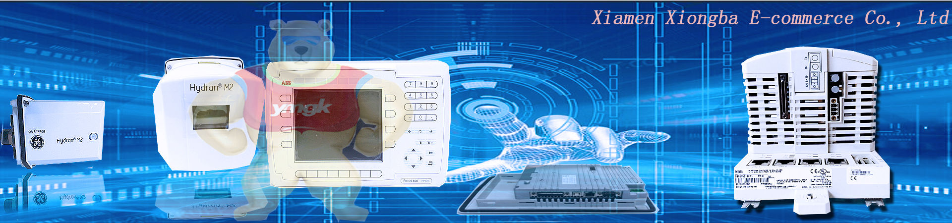
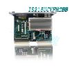
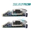
VMIVME-3215-000 Other names:
Control unit VMIVME-3215-000
VMIVME-3215-000 Editable Controller
Input/output module VMIVME-3215-000
VMIVME-3215-000 Analog Controller
PLC control board VMIVME-3215-000
VMIVME-3215-000 is a GE controller. This controller is equipped with a super VGA controller, which uses the 855GME chipset and supports high-resolution graphics and multimedia quality video. The screen resolution can reach up to 1600 x, and the graphics support 1200 true colors (single view mode). This super VGA controller can be accessed through the front panel.
Overview
VMIVME-3115 is a high throughput 12 bit analog input/output (AIO) board that provides four analog inputs, two analog outputs, and dual 8-bit bidirectional digital input/output ports for VMEbus system applications. The dual port data memory, onboard timer, and programmable bus interrupter enable the VMIVME-3115 board to support a wide range of analog input and output flows, with the lowest involvement of the host processor. The sampling and holding input amplifier provides a “snapshot” of all analog inputs simultaneously at a total sampling rate of up to 2MHz, and almost eliminates time offsets between input channels. VMIVME-3115 supports independent and multi board synchronization. Dual analog outputs enable the board to be “closed-loop” in system servo applications. The functional block diagram of VMIVME-3115 is shown in Figure 1.
Simulated input data is stored sequentially in dual 256K byte buffer memory. The host controls which of the two buffers will reside in the VME bus memory through a single switch bit in the control and status register (CSR). When the scanning sequence is completed, the host can also indicate that the board is generating an interrupt. Simulated inputs can be sequentially sorted, synchronized with a single block, or synchronized with multiple boards. In continuous mode, sorting is executed continuously until the host processor stops. In single block synchronization mode, transmit a pre-selected data block and then stop sorting.
Multi board synchronization can be applied in continuous mode or single block mode, with designated boards controlling other VMIVME-3115 boards. Each buffer memory is displayed as 256K bytes of VME bus memory. To simplify automatic system configuration, disable buffers during power on and reset operations. To support multiple VMIVME-3115 boards without requiring additional memory space, the buffer can be completely removed from VMEbus memory through the control bit in the I/O space CSR. The buffer can be jumper located on any 40000 byte (HEX) boundary in the VMEbus memory space. Support block mode D16 data transfer (BLT). Dual analog output channels can drive a 10 mA load within a maximum output range of ± 10 V. Online or offline (disconnect) operations are controlled by the program. Each analog output is directly controlled by a single 16 bit word in the short I/O space of VMEbus.
Functional characteristics
Sequence start: Scanning can be programmed to directly start command trigger events from the host or external TTL. The scanning rate of analog input is controlled by the program. External trigger lines can also be used to synchronize multiple VMIVME-3115 board large analog arrays for simultaneous sampling of signals. For multi board synchronization, the VMIVME-3115 board is designated as the synchronization host, while the remaining boards are designated as slaves. Then the main controller controls the order of all slave boards.
Digital I/O port: The 16 bit parallel digital input and output capabilities are provided by dual 8-bit TTL data ports. Each port can be programmed as an input or output port, and can access the registers of the board found in the controlled short I/O space.
I/O Addressing: It can address 16 consecutive 16 bit registers located on any 16 word boundary in a short-term supervised or short-term non privileged I/O space.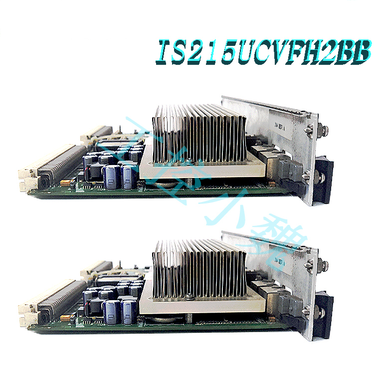
Memory Addressing: Analog to Digital Converter (ADC) buffers are stored in VME hosts like traditional buffers. The total memory space occupied by the board is 256K bytes and can be located on any 40000 bytes (HEX) programBoundaries in VMEbus memory space. This VMIVME-3115 buffer can be removed (masked) from VMEbus memory through CSR control bits. I/O address selection: The short I/O space in the board address is selected by the onboard field with optional jumpers. Any operation is supported except for slot 1.
Access permissions: The address modifier is decoded to support supervision, non privileged, or both. Jumpers are provided to support this feature and are factory provided configurations for any access. The decoded modifier codes include 09, 0A, 0B, 0D, 0E, 0F, 2D, 29, 39, and Figures 3A, 3B, 3D, 3E, and 3F.
VME bus interrupt: VMIVME-3115 can be programmed when any buffer is full. The interrupt response vector is controlled by the onboard interrupt vector register.
Board Identification: The Board Identification Register (BIR) contains the VMIVME-3115 identification code.
Transparent operation: The following default values are established in RESET. Condition: Independent continuous operation. Maximum block size (256 KB). 15.625 kHz. Scanning rate. Analog output. Digital port closed as input
VMEbus compliance: complies with VMEbus specification revision C.1A32/A24/A16: D16/D08 (EO) DTB slave: BLTD16 from interrupter I (1) to I (7) ROAK (DYN) interrupt vector: D08 (O) (DYN) 6U shape factor
Interrupt event: Buffer full. Buffer size (each of 2 buffers): 4 bytes to 256K bytes, with a ratio of 8 to 4:1; Program controlled
VMEbus access: D8 or D16 random access; D16 block mode VMEbus access location: Jumper located at any 4 0000 byte (HEX) boundary of 0000 0000 to FF FC 0000 (hexadecimal)
Control: Disable operations during power on and reset. Enable or disable space CSR through short I/O.
Average access time (selected from data): Block mode: 460 ns at 2 MCPS; 320 ns, or less than 500kCPS
Operation mode: Continuous or single block synchronization:
Independent: continuous or synchronous single block
Multi board: synchronous continuous or synchronous single digital I/O port
Organizational structure: Dual 8-bit bidirectional ports
Logic level: Standard TTL level without inversion VMEbus access: Single 16 bit register space in short I/O, D8 or D16 access
Control: Each port is selected by the program as an input or output port
Physical/Environmental Temperature: 0 to+55 ° C, Operating -40 to+85 ° C, Storage
Relative humidity: 10% to 80%, non condensing
Altitude: Run up to 10000 feet
Size: Standard VME double height board, 160 x 233.35 mm
VME connector: extension ground pins on P1 and page 2
Input/output connectors (P3, P4, P5, J1 to J4): Please refer to ordering information
Power supply:+5.0 VDC+0.25/-0.125 VDC 5.7 A (typical), 7.1 A (maximum)
Applications
Voltage measurement and stimulation
High speed data acquisition
Industrial instruments
Digital signal processing
Development and research
Closed loop control system
Digital inputs and outputs
Phase coherent analog sampling
Trainers and simulators
All products on this website are special products, and market prices have been fluctuating,
The specific customer service quotation shall prevail, as the product is a new product and the price is not genuine,
Please confirm the model, product, price, and other detailed information with customer service before placing an order. The website has been used,
The new one is for sale, please contact customer service to communicate.
Warehouse discount product recommendation:
VMIVME-2533-000
VMIVME-4140-000
VMIVME-5565-010000
VMIVME-5565-110000
VMIVME-7750-734001
VMIVME-7750-734001
VMIVME-7750
VMIVME-7614-132
VMIVME-7740-850
VMIVME-7740-850 350-007740-850 L
More……
-300x300.jpg)
angel –
VMIVME-3115 is a high throughput 12 bit analog input/output (AIO) board that provides four analog inputs, two analog outputs, and dual 8-bit bidirectional digital input/output ports for VMEbus system applications. The dual port data memory, onboard timer, and programmable bus interrupter enable the VMIVME-3115 board to support a wide range of analog input and output flows, with the lowest involvement of the host processor. The sampling and holding input amplifier provides a “snapshot” of all analog inputs simultaneously at a total sampling rate of up to 2MHz, and almost eliminates time offsets between input channels. VMIVME-3115 supports independent and multi board synchronization. Dual analog outputs enable the board to be “closed-loop” in system servo applications. The functional block diagram of VMIVME-3115 is shown in Figure 1.