Description
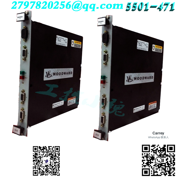
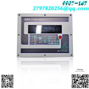
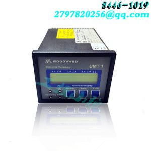
Title : Micronet MODULE Field Termination DISCRETE I/O
MPN : 5466-256
Usage : THE PHOENIX CONTROLS is aware that you need 5466-256 – Micronet MODULE Field Termination DISCRETE I/O – Unused urgently. We will, therefore, work towards expediting your order such that you face no downtime.
Our products are widely used in metallurgy, oil and gas, glass manufacturing, aluminum, petrochemical, coal mining, paper printing, and textile industries
Textile printing and dyeing, machinery, electronic manufacturing, automotive manufacturing, plastic machinery, electricity, water conservancy, water treatment/environmental protection, boiler supply
Heating, energy, power transmission and distribution, etc. Main DCS control system spare parts, PLC system spare parts, and robot system spare parts, I
Advantage brands: Allen Bradley, Bently Nevada, ABB, Emerson Ovation, Honeywell DCS
Rockwell ICS Triplex、FOXBORO、Schneider PLC、GE Fanuc、Motorola、 HIMA、
Various imported industrial components such as TRICONEX and Prosoft
Manufacturer : WOODWARD
If the generator set is equipped with a unit/parallel switch, turn on the conversion to monitor the no-load voltage.
Apply inductive load and pay attention to the voltage drop of the generator.
When R4 is turned to completion, the secondary current of the transformer in the clockwise position with a decrease of about 6% in large resistance and current is one ampere
Connect CT and CT1 or 5 amps to terminals CT and CT5.
16. If the sag exceeds the requirement, rotate R4 counterclockwise. If the droop is less than the desired value, turn R4 clockwise.
Repeat steps 14 to 16 as needed to obtain the desired droop signal
18. To stop the device, remove the load, open the output circuit breaker, and then stop the prime mover.
Manual mode operation: This test is only applicable to generator sets equipped with automatic/manual voltage control options. Typical generator set
The operation of is in automatic voltage control mode. The manual voltage control mode provides a set of operating voltage regulator faults
Set. Test whether manual control is correct during the initial operation of the unit and determine that the cause of the system malfunction is Fault 1.
Execute the previous automatic mode operation program.
2. Open the output circuit breaker, and if it is running, stop starting the porter.
3. If included, turn off the unit/parallel switch.
4. Set the automatic/off/manual selection switch to manual.
Set the manual voltage regulation variable to the full position counterclockwise
6. Start the prime mover and bring it to the rated speed.
7. Adjust the manual voltage regulator to
The correct generator voltage is measured by the generator voltmeter.
8. Adjust the manual voltage regulator to the following position: the voltmeter shows that the generator voltage is about 5% higher than the rated voltage.
9. Close the output circuit breaker and apply the load.
10. Measure the output voltage. If not correct, adjust the voltage adjustment variable in the manual.
11. Repeat steps 8 and 10 each time the load is increased.
12. Before load shedding, reduce the generator voltage by 5% or less for evaluation.


Reviews
There are no reviews yet.