Description
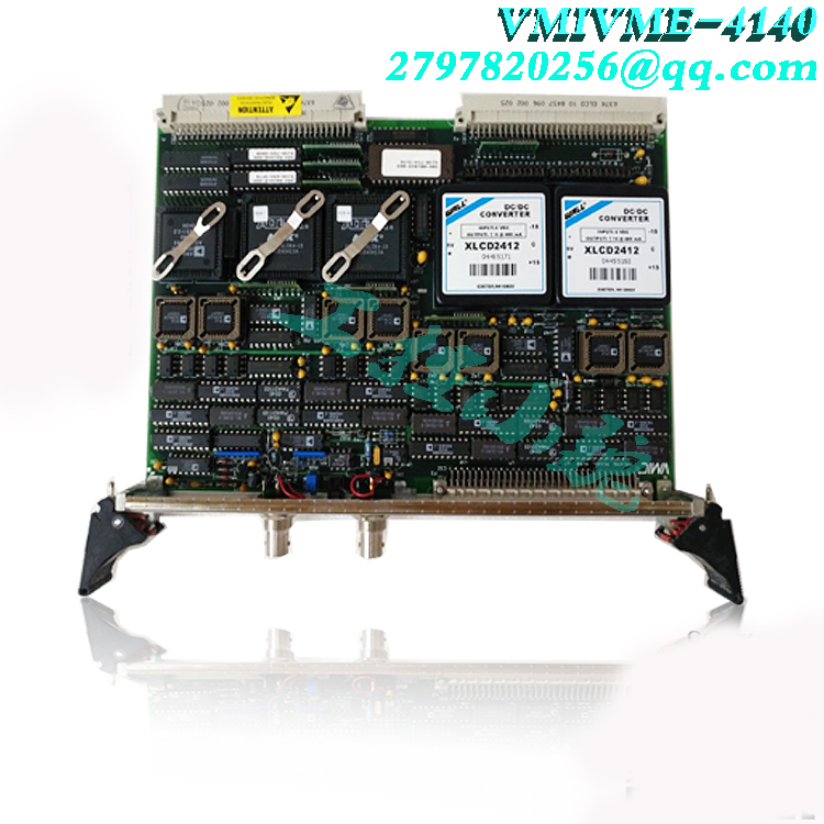
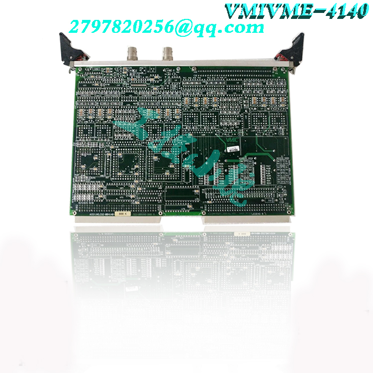
Vibro-meter VM600 series vibration cards
Locking screw: Locks the controller module in the housing. w LEDs: indicates the statuses of controller outputs Y1, Y2 and alarms LIM1, LIM2 (other settings at configuration level C.800 r page 30). w Display 1: indicatess process value at operating and parameter level, or the configuration code at configuration level. w Display 2: indicates the set-point (automatic mode) or the correcting value (manual mode) in operating level. The values are adjustable directly with ID.
Further displays at operating level r page 9. In parameter and configuration level, values and codes described with text1 are indicated (r page 12). w Text 1: indicates the short-form dialogue or the unit of display 2. w Text 2: indicates the output bargraph (other selections possible in configuration level C.800). Keys HDIM: For the certain function r pages 9 and 12. w PC interface: PC connection for configuration/parameter setting/operation with an engineering tool. 2. Safety notes Following the enclosed safety instructions 9499 047 07101 is indispensable! The insulation of the instrument conforms to EN 61 010-1 with pollution degree 2, overvoltage category III,
.jpg)
operating voltage 300 V and protection class I. Additional with horizontal installation, a protection to prevent live part, e.g. wire ends, from dropping into the open housing of a withdrawn controller must be fitted. 3. Electromagnetic compatibility The instrument conforms to European Directive 89/336/EEC and will be provideed with the CE-marking. The following European Generic Standards are met: Emission: EN 50081-2 and Immunity: EN 50082-2. The unit is suitable for use in industrial areas (in residential areas, RF interference may occur). The electromagnetic radiation can be reduced decisively by installing the unit in a grounded metal switch cabinet. Maintenance / Behaviour in case of trouble The controller needs no maintenance. The rules to be followed in case of trouble are:
w Check mains (voltage, frequency and correct connections), w check, if all connections are correct, w check the correct funktion of the sensors and final elements, w check the configuration words for required functions and w check the adjusted parameters for required operation. If the controller still does not work properly after these checks, shut down the controller and replace it. Cleaning:Housing and Front can be cleaned by means of a dry, lint-free cloth. No use of solvents or cleansing agents! 6. Further information A manual with the order no. 9499 040 44811 gives further information to the chapters of this operating notes.S.I.L. switch: with the switch closed, transition to parameter and configuration level is disabled. When making an attempt to change over to the parameter level, ”ParaL” is displayed (text1). Correcting variable, set-point and parameters at the ”extended operating level” remain available for selecting and changing. For access to the S.I.L. switch, release the locking screw and withdraw the instrument module from the housing. Subsequently, re-insert the controller module into the housing and mount it with screws. Protection mode IP65: 4 fixing clamps must be used. The instruments insert must be placed strongly an locked strongly by means of the locking screw. l Caution! The instrument contains ESD-hazarded components. General The KS94 controller configuration for quick and easy function selection during subsequent operation is described in this section. During configuration, the required functions are selected from a large variety of available functions. The configuration determines the basic structure for solution of an application. The configuration structure is designed so that determination of the required functions for a large number of applications is possible by adjustment of as few configuration words as possible. Moreover, the structure was designed flexible enough to permit additional configurations also for realization of special applications. 10.2 Basic structure The first menu level permits selection of the main configuration group. The user can be guided through all function configurations, or he can configure the specific functions required for his application directly. For all ‘complex’ main groups, a two-level configuration concept which enables the user to select the ‘correct’ setting for his application by defining only one configuration word was determined. If necessary, special functions can be determined separately. For the ‘normal user’, however, the configuration words are preset to purposeful default values! For simplification, the hierarchic configuration dialogue is structured so that the user can and must adjust only the ‘required’ configuration words. The user configuration dialogue is started via selector key M and ‘increment’ / ‘decrement’ keys ID, like with the other KS92/94 operating levels: w Press the selector key to select menu items / input values / input positions within a ‘level’ and to change over to the next higher level at the end of a ‘level’. Parameters 11.1 General This section gives a survey of the KS92/94 parameter data and general hints for parameter handling. The parameter operation and effect on the controller operation are described with the operating principle. The parameter setting dialogue is realized via selector key M and ‘increment’ / ‘decrement’ keys ID, like at the other operating levels: w Press the selector key to select menu items / input values within one level and to change to the next higher level. w Press the ‘increment’ / ‘decrement’ keys to return to a lower level or to change input values. The controller parameter structure is given on the following page. All parameters are listed. Parameters which are not relevant for a function (configuration-dependent) are not displayed! A selection menu can be displayed anywhere at parameter level by pressing key M >3s. End: return to parameter level Mark: mark the selected parameter for display at ‘extended’ configuration level. Exit: return to operating level. Conf: transition to configuration level.Allocation of parameters to the ‘extended operating level’ Up to 12 parameters can be allocated to the ‘extended operating level’ (see Fig.3: ), whereby the controller operation is simplified, since changing over to parameter level whenever one of these parameters must be changed is omitted. Allocation: select required parameter, press ‘selection’ key M during >3s (Para blinks) Select Mark with ‘up’ key I and acknowledge with ‘selection’ key M (see Fig.3: ). Delete: select the required parameter at the extended operating level, press ’selection’ key M during >3s (Para blinks) and acknowledge with ’up’ key I. Select Clear and acknowledge with ‘selection’ key M (see Fig.4: ). Hold: The Hold function can be used for selecting a parameter from the extended operating level for being visible continuously. For this, select the required parameter at the extended operating level, press ‘selection’ key M during >3s (Para blinks) select Hold with ‘up’ key I and confirm with ’selection’ key M (see Fig.4:). Applications: w During optimization, frequent access to defined parameters (Xp1, Xp2, Tn and Tv) is required. w During commissioning, limit value ( LimH1, LimH2, …) or measurement value corrections must be changed frequently. w With the parameter level disabled, access to the selected parameters is possible for the operator. Deleting a parameter from the ‘extended operating level’ must be done at this level (see Fig.4: )
Model recommendation:

-100x100.jpg)

Reviews
There are no reviews yet.