
Description
SPECIFICATIONS Part Number9905-463 ManufacturersWoodward Sub-CategoryPLC Module
These controls are available for forward- or reverse-acting applications, and for use with either single or tandem actuators. Models for three different actuator current ranges are available, as well as a high-voltage model (90 to 150 Vdc or 88 to 132 Vac, 45 to 440 Hz), and a low-voltage model (20 to 40 Vdc). The high voltage model is identified as such on the front; the low voltage model is not. In reverse-acting systems,
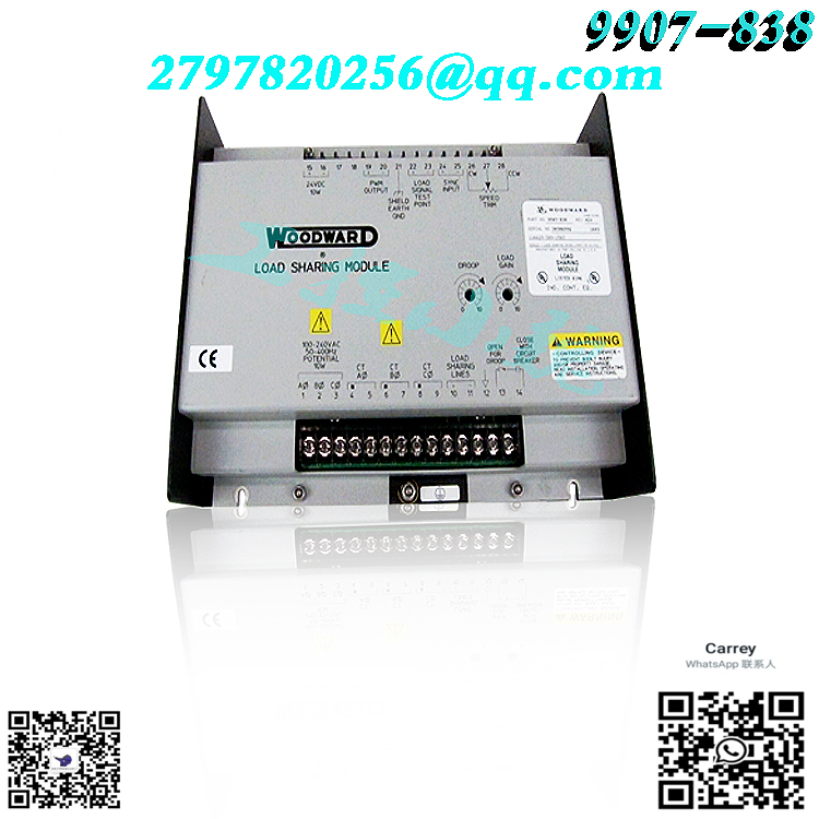
the actuator calls for more fuel when the actuator voltage decreases. Complete loss of voltage to the actuator will drive the actuator to full fuel. This allows a backup mechanical ballhead governor to take control rather than shut down the prime mover as would a direct-acting system. An optional deceleration ramp is also offered. When this option is present, the time to ramp from rated speed to idle speed is approximately 20 seconds. If this option is not present, this happens instantly. Tables 1-1 and 1-2 show part numbers and features of all 9905/9907 series 2301A load sharing and speed controls.The relationship between prime mover speed and sensor output frequency is expressed in the formula: Sensor Frequency in Hz equals the number of teeth on the speed sensing gear times the rated prime mover speed in revolutions per minute divided by 60.
.jpg)
Application engineers from Woodward or any of its authorized distributors or agents are always available to assist you in selection of the correct control for your system, or to answer questions concerning control installation, operation, or calibration. See Chapter 6 for contact information. References The following publications contain additional product or installation information on Load Sharing and Speed Controls, and related components. They are available on the Woodward website (www.woodward.com/ic). technical manual title 25070 Electronic Governor Installation Guide 26260 Governing Fundamentals and Power Management 82384 SPM-A Synchronizer 9905-002 82510 Magnetic Pickups & Proximity Switches for Electronic Controls 82715 Guide for Handling and Protection of Electronic Controls, Printed Circuit Boards, and Modules product specification title 82383 SPM-A Synchronizer 82390 2301A Load Sharing and Speed Controls (9905 Series) 82516 EG3P/6P/10P Actuator 82575 EGB1P/2P Governor/ActuatorAll shielded cable must be twisted conductor pairs. Do not attempt to tin (solder) the braided shield. All signal lines should be shielded to prevent picking up stray signals from adjacent equipment. Connect the shields to the control terminals as shown in Figure 2-1 and in the plant wiring diagram (Figure 1-2). Wire exposed beyond the shield should be as short as possible, not exceeding 50 mm (2 inches).
.jpg)
The other end of the shields must be left open and insulated from any other conductor. Do not run shielded signal wires with other wires carrying large currents. See Woodward application note 50532, EMI Control for Electronic Governing Systems, for more information. Where shielded cable is required, cut the cable to the desired length and prepare the cable as instructed below and shown in Figure 2-1. 1. Strip outer insulation from BOTH ENDS, exposing the braided or spiral wrapped shield. DO NOT CUT THE SHIELD. 2. Using a sharp, pointed tool, carefully spread the strands of the shield. 3. Pull inner conductor(s) out of the shield. If shield is the braided type, twist to prevent fraying. 4. Remove 6 mm (1/4 inch) of insulation from the inner conductor(s). 5. Connect wiring and shield as shown. In installations with severe electromagnetic interference (EMI), shielded wire run in conduit, double shielded wire, or other precautions may be required. Contact Woodward for more information. Droop Contact (Isoch-Droop) and Load Sharing Lines Because the load-sharing-line relay is contained in the control, no relay is required between the control and the load-sharing-line bus. Use shielded cable and connect the load-sharing lines directly to terminals 10 (+) and 11 (–). Connect the shield to terminal 12. When all controls in the system are of the 2301A type, the shields may be connected continuously between controls. When load sharing with different controls, do not connect the shields at the point where connections are made to the load-sharing-line bus. The droop contact for selecting droop or isochronous operation is wired in series with the circuit-breaker auxiliary contact between terminal 14 and terminal 16 (terminal 0 on high-voltage controls). When both the droop contact and circuitbreaker auxiliary contact are closed, the control is in the isochronous loadsharing mode (Figure 2-3, A). In this mode, the internal load-sharing-line relay is energized, the droop signal is disabled (permitting isochronous load sharing), and the load-matching circuit is connected to the load-sharing lines. The control is in the droop mode when EITHER the droop contact or the circuitbreaker auxiliary contact is open (Figure 2-3, B). If the droop contact is open, the control remains in the droop mode even when the circuit-breaker auxiliary contact is closed.
Model recommendation:
WOODWARD 9905-969


Reviews
There are no reviews yet.