Description
Product Description
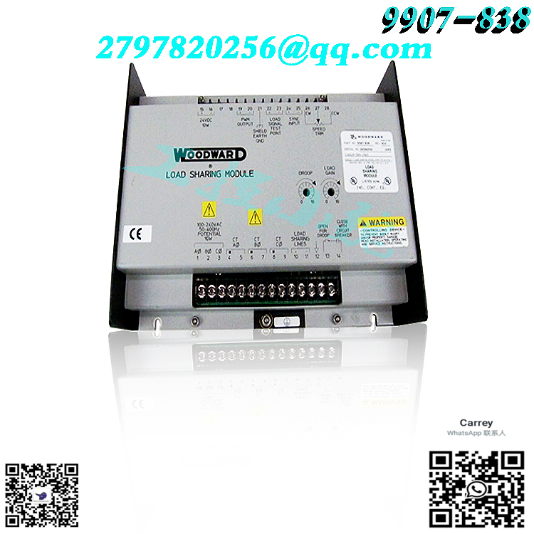
The Woodward 9907-205 is a handheld programmer. The models 9907-205 are part of the MSLC series or main synchronizer and load control series produced by Woodward Inc. The 9907-205 has multiple functions. Some tasks within its scope of authority include synchronization, utility load sensing, control capabilities for input and output load levels, power factor, and main process control capabilities.
The 9907-205 model is designed as an MSLC handheld programmer module. This enables the operator to monitor the standard parameters of the generator and diagnose its contact switches and analog input and output ports. By allowing users to set control functions and specifications before the system is powered on, it also helps to reduce the time spent on installation and troubleshooting.
Pay attention to potential or technical issues during operation, and one of the possible technical issues that may arise during operation is the remote load reference input. You can run so-called bench tests to ensure that your controls are functioning properly. The test you will perform to check the remote load reference input should ensure correct operation and calibration. If you need to calibrate remote input, you should enter the calibration menu and select option 6 and set the key to 49.
This chapter provides an overview of the features and operation of the ProAct™ Digital Speed Control and Actuator system. Figure 1-4 shows the actuator outline. Figure 1-5 is the wiring diagram for reference in the following descriptions. Figure 1-3 is a schematic cutaway view of the ProAct II actuator. The ProAct Digital Speed Control uses a 16-bit microprocessor for all control functions, such as computing engine speed, performing the control algorithm calculations, speed ramps, etc. All control adjustments are made with a hand held terminal/display (see Figure 4-1) that communicates with the control via a serial port. The terminal/display is disconnected from the control when not in service to provide security against tampering. The operating program is adjusted through seven menus accessed through the hand held terminal display. Details of these seven menus are contained in Chapter 4 of this manual. The speed sensor contains a special tracking filter, designed for reciprocating engines, which minimizes the effects of engine torsionals or irregularities in the gear used for sensing speed. This provides exceptionally smooth steady-state control and allows the control dynamics to be matched to the engine. The speed signal itself is usually provided by a magnetic pickup supplying an AC signal from 1 to 60 Vrms to the control. The frequency (in Hz) is proportional to engine rpm. The control features exceptional spike, ripple, and EMI (electromagnetic interference) rejection. Discrete inputs are optically isolated and capable of rejecting EMI and variable resistances in switch or relay contacts. Analog inputs are differential-type with extra filtering for common-mode noise rejection. This protects the control from spurious interference and noise which can cause speed and load shifts. The chassis should be bolted to a good ground to ensure effective EMI/RFI protection. An auxiliary ±2.5 volt input is provided to interface with Woodward Load Sensors, to provide isochronous load-sharing operation. Alternate Dynamics The ProAct control provides two complete sets of dynamic adjustments, which are externally switch selectable. The two sets of dynamics are provided for use where engine operating conditions change, such as in systems which use two different fuels, clutched-in loads, and electrical power generation where the unit may be operated stand-alone and paralleled with an infinite bus. Each set of dynamics provides different gain mapping, stability, compensation, gain ratio, and gain window settings. This allows instantaneous changes in control for engines which operate with different fuels or have load-type changes which require different dynamics. Gain Ratio is the ratio of Gain setting during transient off-speed conditions to the gain setting at steady state. Speed Gain Ratio operates by multiplying the Gain set point by the Gain Ratio when the speed error is anticipated to be greater than the Window Width. This allows a lower gain at steady state for better stability and reduced steady-state actuator movement (see Figure 2-1).
.jpg)
All electronic equipment is static-sensitive, some components more than others. To protect these components from static damage, you must take special precautions to minimize or eliminate electrostatic discharges. Follow these precautions when working with or near the control. 1. Before doing maintenance on the electronic control, discharge the static electricity on your body to ground by touching and holding a grounded metal object (pipes, cabinets, equipment, etc.). 2. Avoid the build-up of static electricity on your body by not wearing clothing made of synthetic materials. Wear cotton or cotton-blend materials as much as possible because these do not store static electric charges as much as synthetics. 3. Keep plastic, vinyl, and Styrofoam materials (such as plastic or Styrofoam cups, cup holders, cigarette packages, cellophane wrappers, vinyl books or folders, plastic bottles, and plastic ash trays) away from the control, the modules, and the work area as much as possible. 4. Do not remove the printed circuit board (PCB) from the control cabinet unless absolutely necessary. If you must remove the PCB from the control cabinet, follow these precautions: • Do not touch any part of the PCB except the edges. • Do not touch the electrical conductors, the connectors, or the components with conductive devices or with your hands. • When replacing a PCB, keep the new PCB in the plastic antistatic protective bag it comes in until you are ready to install it. Immediately after removing the old PCB from the control cabinet, place it in the antistatic protective bag.
Idle/Rated Contact The Idle/Rated contact (open for Idle, closed for Rated) connects to terminal 10, Discrete Input B. This contact also determines which fuel limiter is in effect. In Idle, the control uses the Start Fuel Limit set point. In Rated, the control uses the Maximum Fuel Limit set point or Torque Limit schedule. When the Idle/Rated contact is closed, the control immediately switches the fuel limit to the maximum limit and ramps engine speed to the rated speed set point (or the speed specified by the Remote Input when the Remote Speed Setting input is enabled). When the Idle/Rated contact is opened, the control immediately switches on the Start Fuel Limit and ramps engine speed to the idle speed setting. The idle set point cannot be set above the rated set point. The fuel limiters (start or maximum) remain effective regardless of the Local/Remote input. Lower Speed Contact The Lower Speed contact connects to terminal 11, Discrete Input C. When the Lower Speed contact is closed, the control lowers speed at a rate determined by the Lower Rate set point. When the contact is open, speed remains at its current value. Actuating the Lower Speed contact will cancel the ramps started by the Idle/Rated contact. The Lower Speed contact input is disabled when the Remote Speed Setting mode is selected by closing both the Lower Speed and Raise Speed contacts. Raise Speed Contact The Raise Speed contact connects to terminal 12, Discrete Input D. When the Raise Speed contact is closed, the control raises speed at a rate determined by the Raise Rate set point. When the contact is open, speed remains at its current value. Actuating the Raise Speed contact will cancel the ramps started by the Idle/Rated contact. The Raise Speed contact input is disabled when the Remote Speed Setting mode is selected by closing both the Lower Speed and Raise Speed contacts. Alternate Dynamics The Alternate Dynamics contact connects to terminal 13, Discrete Input E. When this contact is open, Dynamics set 1 is selected. When this contact is closed, Dynamics set 2 is selected. Failed Speed Signal Override The Failed Speed Signal Override is connected to terminal 14, Discrete Input F. When the contact is open, the control operates normally, turning the control output to minimum fuel in the event of a loss of speed signal. Closing the contact overrides the failed speed signal function, which may be required for start-up. Prior to engine start-up, the speed signal is nonexistent. On engines requiring fuel during cranking, the Failed Speed Signal Override allows the actuator to open and provide fuel for starting. menu. To step through the menu, use the “Up Arrow” and “Down Arrow” keys (the “Left Arrow” and “Right Arrow” keys perform the same functions). The “Down Arrow” key advances through the menu and the “Up Arrow” key moves backward through the menu. The menus are continuous; that is, pressing the “Down Arrow” at the last menu item takes the menu to the first item, or pressing the “Up Arrow” at the beginning of the menu takes the menu to the last item. To adjust a set point, use the “Turtle Up” or the “Rabbit Up” keys to increase the value, and the “Turtle Down” or “Rabbit Down” keys to decrease the value. The “Rabbit Up” and “Rabbit Down” keys will make the rate of change faster than the “Turtle Up” and “Turtle Down” keys. This is useful during initial setup where a value may need to be changed significantly. Finally, use the “SAVE” key to save entered values. After you are satisfied with all entries and adjustments, press the “SAVE” key to transfer all new set point values into EEPROM memory. The EEPROM retains all set points when power is removed from the control. Menu 1 — Dynamics Menu Menu 2 — Alternate Dynamics Menu Dynamic adjustments are settings that affect the stability and transient performance of the engine. There are two sets of dynamics provided.
.jpg)
The set being used is selected by the Alternate Dynamics Contact input. The following descriptions of each menu item apply to either set. Also see Figures 4-2, 4-3, and 4-4. 1. Gain determines how fast the control responds to an error in engine speed from the speed-reference setting. The gain is set to provide stable control of the engine at light or unloaded conditions. 2. Stability compensates for the lag time of the engine. It adjusts the time required for the control to return the speed to zero error after a disturbance. Stability is adjusted to prevent slow hunting and to minimize speed overshoot after a load disturbance. 3. Compensation compensates for the actuator time constant. 4. Gain Ratio is the ratio of the Gain setting at steady state to the Gain setting during transient conditions. The Gain Ratio operates in conjunction with the Window Width and Gain adjustments by multiplying the Gain set point by the Gain Ratio when the speed error is greater than the Window Width. This makes the control dynamics fast enough to minimize engine-speed overshoot on start-up and to reduce the magnitude of speed error when loads are changing. This allows a lower gain at steady state for better stability and reduced steady-state actuator linkage movement. 5. Window Width is the magnitude (in rpm) of a speed error at which the control automatically switches to fast response. The control does not use the absolute value of speed error, but “anticipated” speed error to make this switch. This method provides for quick switching to the high gain value when an offspeed occurs and early switching to the low gain value when recovering from the speed transient. This provides smoother switching than if the absolute speed error was used for the window. 6. Gain Breakpoint sets the percent output above which the Gain Slope becomes effective. It should usually be set just above the minimum load output. 7. Gain Slope changes Gain as a function of actuator output. Since actuator output is proportional to engine load, this makes gain a function of engine load. Gain Slope operates in conjunction with the Gain Breakpoint adjustment to increase (or decrease) gain when percent actuator output is greater than the breakpoint. This compensates for systems having high (or low) gain at low load levels. This allows the Gain setting to be lower at light or no load for engine stability, yet provide good control performance under loaded conditions.
Menu 4 — Fuel Limiters and Control Output Menu Fuel limiters limit the actuator output current from the control. Descriptions of each menu item follow. 1. Max Fuel Limit sets the maximum percent actuator output current when rated speed is selected. Maximum (100%) is based on 200 mA (100% is based on 20 mA for the 20 mA output version of the 701A). The limit is usually set just above the output at full load. The percent output is displayed on Menu 7. 2. Start Fuel Limit sets the maximum percent actuator output current when at the start speed specified below. The limit is usually set at the fuel level required to start the engine. 3. Start Speed is the engine speed at which ignition usually occurs during engine start-up. When an engine speed is below the Start Speed setting, the maximum percent actuator current is determined by the Start Fuel Limit. When the engine accelerates between Start Speed and Idle Speed, the maximum current is ramped to the Idle Fuel Limit in proportion to speed. 4. Idle Fuel Limit sets the maximum percent actuator output current when the engine is operated at idle. During engine start-up, the maximum fuel is increased (or decreased if Idle Fuel Limit is less than the Start Fuel Limit) from the Start Fuel Limit to the Idle Fuel Limit in proportion to the engine speed. For initial start, set this at 100% to deactivate. The Idle Fuel Limit allows the fuel limit to ramp from the Start Fuel Limit, to the Idle Fuel Limit, to the Max Fuel Limit, to provide smoother transitions and less overfueling. Their use is optional. 5. Torque Limit BP (breakpoint) is the engine speed at which the slope of the torque limiter output changes. The Torque Limit Breakpoint must be set between the Raise and Lower Limits described under Menu B above. 6. Min Torque Limit is the percent actuator output current allowed when the engine speed is at or below the Lower Limit speed setting (Menu B Lower Limit set point above). The torque limiter interpolates between Minimum Torque Limit and Breakpoint Torque Limit when engine speed is between these two settings. 7. BP (breakpoint) Torque Limit is the percent actuator output current at the engine speed set by the Torque Limit Breakpoint described above. 8. Max Torque Limit is the maximum percent actuator output current when the engine speed is at the Raise Limit speed setting. The torque limiter interpolates between the Breakpoint Torque Limit and Maximum Torque Limit when engine speed is between these two settings. Figure 4-5 illustrates the breakpoint and these adjustments. 9. 20ma Aux Actuator Output is the actuator percent corresponding to full scale on the user-supplied actuator position meter (20 mA output from the control; see Menu 1, Aux Output Configuration). 10. 4ma Aux Actuator Output is the actuator percent when corresponding to minimum scale on the user-supplied actuator position meter (4 mA output from the control; see Menu 1, Aux Output Configuration).
Model recommendation:
WOODWARD 9907-018
WOODWARD 9907-163
-300x300.jpg)
Reviews
There are no reviews yet.